CLUTCHING
6.14
NOTE: Pinch thesheaves lightly togetherwithclamp
to prevent the belt from being pushed into the driven
sheave.
1. Place a straight edge on top of the belt between
drive and driven clutch.
2. Pushdownondrivebeltuntilitis lightlytensioned.
3. Measure belt deflection as shown in photo.
NOTE: If belt deflection is out of specification, adjust
by removing or adding shims between the driven
clutch sheaves.
G Remove shims to decrease belt
deflection
G Add shimstoincreasebelt deflection
See DRIVEN CLUTCH
DISASSEMBLY/INSPECTION, Pages 6.19 - 6.20.
NOTE: At least one shim must remain between the
inner and outer sheave of the driven clutch. If proper
beltdeflectioncannot beobtained, measuredrivebelt
width, length, and center distance of drive and driven
clutch, outlined in this section; all have an effect on
belt deflection.
DRIVE BELT
REMOV
AL/INSPECTION
1. Remove outer PVT cover as described in PVT
Disassembly.
2. Mark drive belt direction of rotation so that it can
be installed in the same direction. NOTE:
Normally positioned so part numbers are easily
read.
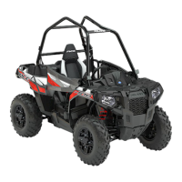
3. To remove drive belt: apply brake, pull upward
and rearward on belt to open driven clutch
sheaves, pullout anddownonbelt toslip overthe
driven clutch outer sheave.
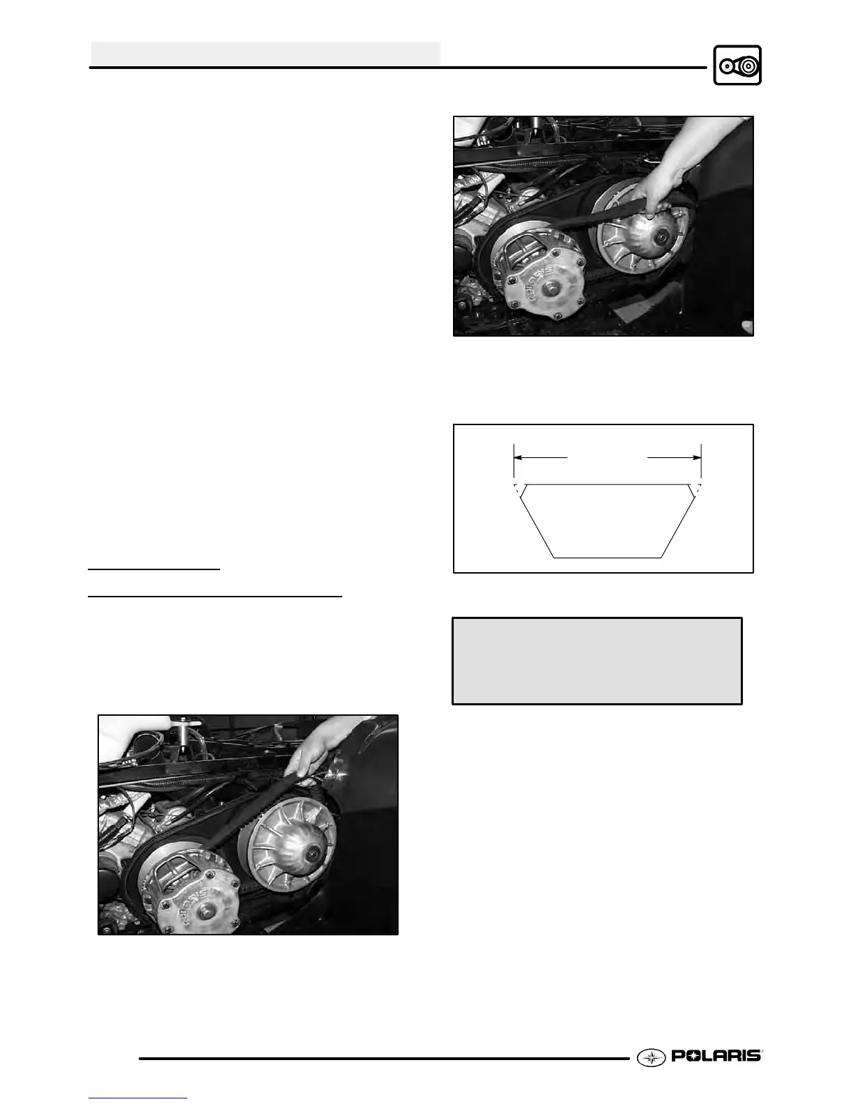
Projected Belt
Width
Belt Width:
New 1.174 - 1.188″ (2.98-3.02 cm)
Wear Limit 1.125″ (2.86 cm)
4. Measure belt width and replace if worn severely.
Generally, belt should be replacedif clutches can
no longer be adjusted to provide proper belt
deflection.
G Thetopedgeshavebeentrimmedon
somedrivebelts. Itwillbenecessary
to project the side profiles and
measure from corner to corner.
G Placea straightedge oneach sideof
the drive belt.
G Placeanother straight edgeon topof
belt.
G Measurethedistancewheretheside
straight edges intersect the top, as
shown in the illustration below.

 Loading...