MAINTENANCE
2.29
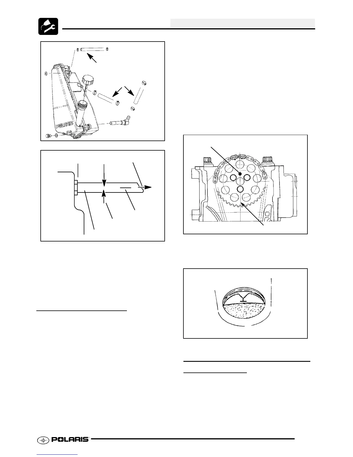
Oil Lines
To Engine
(A) Vent Hose to Air Box
Slit
Oil Tank
Vent Hose
To Air Box
Pinch Off
2I
Approx.
2. Run engine for 10-20 seconds.
3. Shut engine off. Remove the vent line clamp. A
rushofairshouldbeheard,indicatingtheoilpump
is properly primed and ready for field operation.
Note: Ifthesystem is primedproperlyyoushould
hear some air release. If you do not, the system
has not primed. Repeat theprocess if necessary.
VALVE CLEARANCE
Inspect and adjust valve clearance while the engine
is cold and the piston positioned at Top Dead Center
(TDC) on compression stroke.
1. Remove the seat.
2. Remove body panels and fuel tank as necessary
to gain access to valve cover.
3. Remove the spark plug high tension lead and
removethesparkplug. CAUTION: Placeaclean
shop towel into the spark plug cavity to prevent
dirt from entering.
4. Remove rocker cover bolts, cover and gasket.
NOTE: It may be necessary to tap cover lightly
with a soft-faced hammer to loosen it from the
cylinder head.
5. Remove timing inspection plug from recoil
housing.
CAUTION: Failure to position the crankshaft at TDC
on compression stroke will result in improper valve
adjustment.
6. Rotate engine slowly with recoil rope, watching
the intake valve(s) open and close.
NOTE: At this point watch the camshaft sprocket
locating pin and slowly rotate engine until locatingpin
is facing upward, directly in line with the crankshaft to
camshaft center line as shown. The camshaft lobes
should be pointing downward.
Sprocket alignment pin facing up
Crankshaft-to-Camshaft Centerline
7. Verify accurate TDC positioningby observingthe
“T” mark aligned with the pointer in the timing
inspection hole. In this position there should be
clearance on all valves.
INTAKE VALVE CLEARANCE
ADJUSTMENT
1. Insert a .006″ (.15mm) feeler gauge betweenend
of intake valve stem and clearance adjuster
screw. Note: Do not stack more than one feeler
gauge to make .006″.
2. Usinga 10 mm wrenchand a screwdriver, loosen
adjuster lock nut and turn adjusting screw until
there is a slight drag on the feeler gauge.

 Loading...