CLUTCHING
6.11
DRIVE CLUTCH
DISASSEMBL
Y
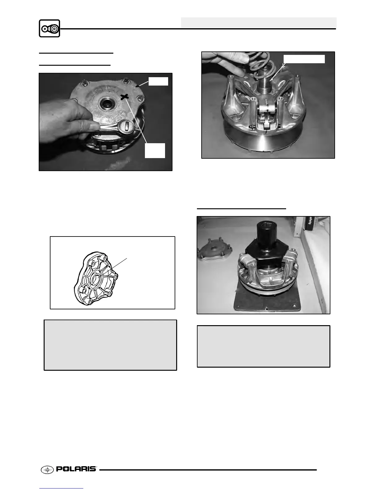
Mark
“X”
Mark
1. Using a permanent marker, mark the cover,
spider , moveable and stationary sheaves, and
steel post to the stationary sheave for reference.
The X’s may not have been in alignment before
disassembly.
2. Removecoverboltsevenlyinacrosspattern,and
remove cover plate.
A
Cover Bushing Inspection:
Replace the cover bushing if more
brass than Teflont is visible on
the bushing. Refer to bushing re-
placement in this chapter.
3. Inspect cover bushing (A). The outer cover
bushing is manufactured with a Teflont coating.
Bushing wear is determined by the amount of
Teflont remaining on the bushing.
Inspect shaft
4. Inspect area on shaft where bushing rides for
wear, galling,nicks, orscratches. Replaceclutch
assembly if worn or damaged.
5. Remove and inspect spring. (See Page 6.8)
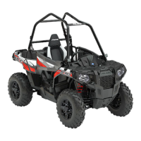
SPIDER REMOVAL
Clutch Holding Fixture:
(PN 2871358)
Spider Removal Tool:
(PN 2870341)
1. Install clutch in holding fixture and loosen the
spider (counterclockwise) using spider removal
tool.
NOTE: It is important that the same number and
thickness of washers are reinstalled beneath the
spider during assembly. Be sure to note the number
and thickness of these washers.