FINAL DRIVE
7.7
MAGNETIC COIL REMOVAL
1. Remove the front drive axle as described later in
this chapter .
2. Remove the seal sleeve from the strut casting
using a drift punch and hammer , tapping evenly
on each side until the sleeve slides off.
3. Remove the existing coil and clean the coil wire
channel, coil mount area, and the seal sleeve
mounting area of all silicone and foreign matter.
4. Disconnect the coil wires at the connector or
terminal board.
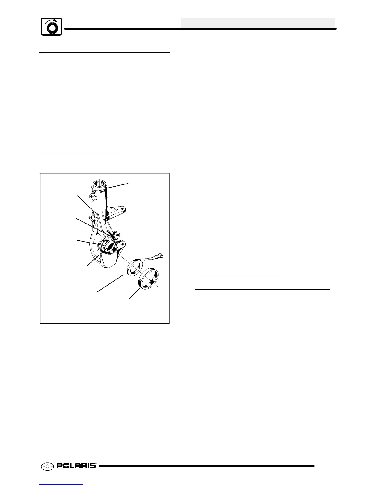
MAGNETIC COIL
INSTALLA
TION
Brake Line
Clip Location
Strut Ribs
Coil Wire
Channel
Seal
Sleeve
Mounting
Area
Coil Mounting
Surface
(Inner Magnet
Pole)
(Fixed)
Electromagnet Coil
Seal Sleeve (Outer Magnet Pole)
(Adjustable) Must use Seal Sleeve
Installation Tool Kit (PN 2871199)
1. Apply1/4I(.6 cm) bead of silicone in the coil wire
channel.
2. Install thecoil tothe coil mount surface andpress
the coil wires into the silicone in the coil wire
channel.
3. Apply 1/4I (.6 cm) bead of Loctitet Ultra Blue
silicone around the seal sleeve mounting area.
NOTE: This includes applying silicone over the
coilleadwires again. Always allow12hours’cure
time for silicone.
4. Press on the seal sleeve until even with the inner
pole. See Page 7.17 for additional information.
Once the seal sleeve is properly positioned, a
1/16I (.16 cm) bead of silicone should remain
around the inner edge. Clean off all excess
silicone. The seal sleeve area must be free of
silicone or the hub seal may leak.
NOTE:
S Always install a new seal sleeve
when replacing the coil. Use Seal
Sleeve Installation Tool Kit (PN
2871199).
S It may be necessary to apply more
silicone (or an equivalent fast drying
glue) to the wire channel area to
properly secure and protect the coil
wires.
S Apply 401 Loctitet to the inside of
the strut ribs and press the foam
block to containthe coil wires. Make
sure thefoam block is bonded well to
protect the coil wires.
NOTE: Coil wires must be contained in the brakeline
clipon thebacksideof theupper strutcastingandthe
wires must be snug against the casting.
5. Route the wires smoothly and away from any
moving parts and secure in place with tie straps.
6. Assemble front axle and connect hub wires.
HILLIARD CLUTCH
DISASSEMBL
Y/INSPECTION
1. Remove front hub.
2. Remove Hilliard clutch assembly.
3. Disassemble the roller clutch and thoroughly
clean all parts. CAUTION: Do not remove the
garter spring. If the spring is removed, it will
become over stressed and will require
replacement.
4. Inspect rollcage sliding surface (A). Thissurface
must be clean and free of nicks, burrs or
scratches. Inspect roller cage (2) carefully for
cracks.
5. Inspect rollers (3). The rollers must slide up and
down freely within the roller cage sliding surfaces
A.

 Loading...