ENGINE
3.36
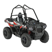
2. Note the alignment dots on the balancer and
crankshaft gears, the marks must be aligned
during reassembly.
3. Turntheshaftuntilbalancercounterweightsclear
the crankshaft and remove the balancer shaft
from the crankcase.
4. Inspect the balancer drive gear and pump shaft
drive gear.
5. Replace the shaft if gear teeth are abnormally
worn or damaged.
6. Inspect the balancer shaft bearings.
NOTE: Due to extremely close tolerances and
minimal wear, the balancer shaft ball bearings must
be inspected visually and by feel. Look for signs of
discoloration, scoring or galling. Turn the inner race
of each bearing. The bearings should turn smoothly
and quietly. The outer race of each bearing shouldfit
tightlyinthecrankcase. The inner race shouldbefirm
withminimalsidetosidemovementandnodetectable
up and down movement.
CRANKSHAFT
REMOVAL/INSPECTION
A
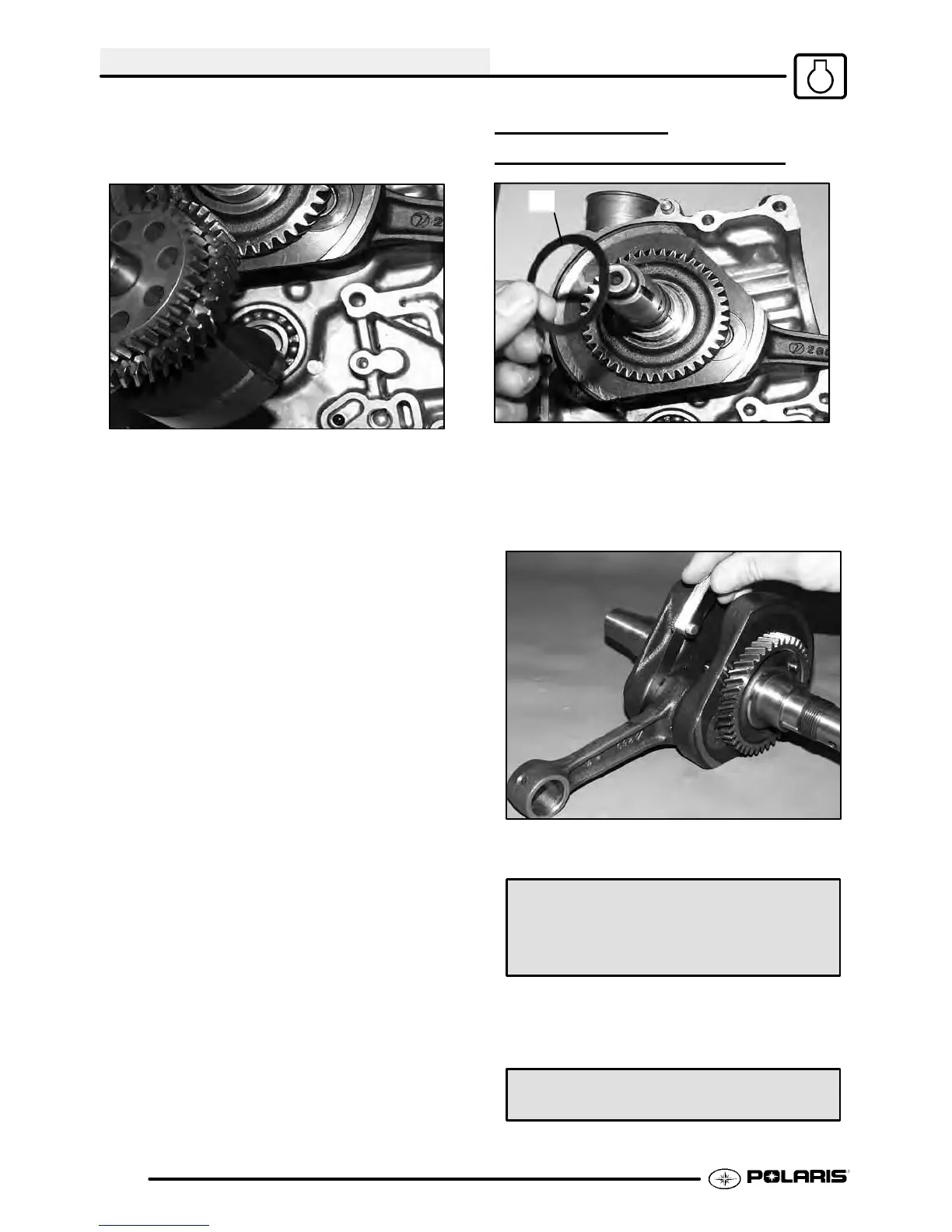
1. Removetheshimwasher(A)fromthecrankshaft.
2. Support the PTO sidecrankcase and crankshaft;
press the crankshaft out. Be careful not to
damage the crankcase mating surface or
connecting rod.
3. Useafeelergaugetomeasuretheconnectingrod
big end side clearance.
Connecting Rod Big End Side Clearance:
Std: .0039-.0256I (.1- .65 mm)
Limit: .0315I (.80 mm)
4. Place the crankshaft in a truingstand or V-blocks
and measure the runout on both ends with a dial
indicator.
Max Runout: .0024″ (.06 mm)

 Loading...