Home
Polaris
Offroad Vehicle
IQ 2007
Polaris IQ 2007 User Manual
5
of 1
of 1 rating
325 pages
Give review
Manual
Specs
To Next Page
To Next Page
To Previous Page
To Previous Page
Loading...
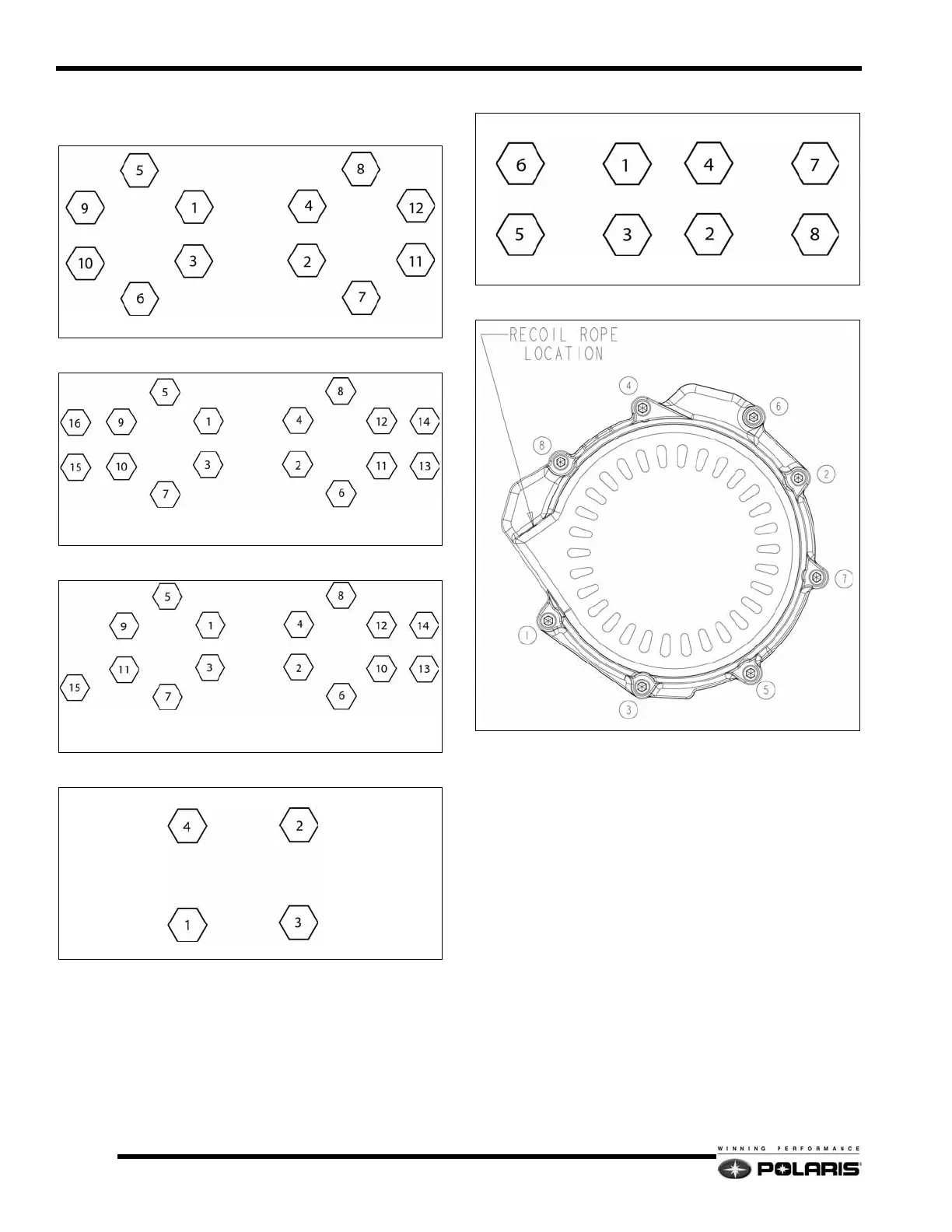
5.4
Engine and Cooling Systems
Component T
orque Sequences
Cylinder Head Torque Pattern (All)
CFI Crankcase T
orque Pattern
Carbureted
Crankcase
T
orq
ue Pattern
Cylinder T
orque Pattern (Except Monoblock)
Cylinder T
orque Pattern (Mono
block)
CFI Recoil Cover
MAG
PTO
MAG
PTO
MAG
PTO
MAG
PTO
MAG
PTO
122
124
Table of Contents
Model Specifications Chapter 1 1
4
Table of Contents
4
2007 600 Ho Iq
5
Chapter 1
5
Model Specifications
5
Specifications
5
2007 600 Ho Switchback
7
2007 600 Ho Rmk
9
2007 600 Ho Iq Cfi
11
2007 600 Ho Switchback Cfi
13
2007 600 Ho Iq Lx Cfi
15
2007 600 Ho Iq Touring Cfi
17
2007 700 Ho Iq Dragon
19
2007 700 Ho Rmk Dragon
21
2008 Iq Shift
23
2008 600 Rmk 144 / 600 Rmk Shift 155
25
2008 600 Dragon Iq
27
2008 600 Switchback / 600 Dragon Switchback
29
2008 600 Iq Lx
31
2008 600 Iq Touring
33
2008 600 Rmk 155
35
2008 700 Iq / 700 Dragon Iq
37
2008 700 Switchback / 700 Dragon Switchback
39
Dragon Rmk 155 / 163
43
General Information Chapter 2 General Information 2
46
Chapter 2 Model Number Designation
47
Snowmobile Number Designations
47
Vehicle Identification Number (Vin)
48
Tunnel Decal
48
Vin Number Designation
48
Publication Part Numbers
49
2008 Publications
49
Engine Data Formulas
50
Compression Ratio
50
Compression Ratio Example
51
Head CC Removal Example
51
Port Opening Duration
51
Torque Conversion
52
Us to Metric
52
General Reference
53
Standard Bolt Torque Specification
53
Fuel / Oil Premix Ratios
53
Gasoline Volatility
53
Sae Tap Drill Sizes
54
Metric Tap Drill Sizes
54
Decimal Equivalents
54
Measurement Conversion Chart
55
Piston Wash / Spark Plug Reading
55
Service Precautions
56
General Precautions
56
Maintenance Chapter 3 Maintenance
58
Maintenance
58
Periodic Maintenance
59
Chapter 3 Periodic Maintenance Schedule
59
Fuel Systems
59
Maintenance Products
61
Engine Oils / Lubricants / Misc
61
Drive / Driven Clutches
62
Belt Deflection Inspection
62
Deflection Adjustment - Team Driven
62
Torque Stop Adjustment
63
Engine Isolator Limiter Setting
63
Engine Maintenance
64
Exhaust Valve Cleaning
64
Surge Tank
64
Recommended Coolant
64
Cooling System Bleeding
64
Oil Pump Adjustment - Carbureted Models
65
Oil Pump Adjustment - Cfi Models
66
Oil Pump Bleeding
68
Fuel / Intake System
68
Water Sediment Trap
68
Fuel Filter - Carbureted Models
68
Fuel Filter - Cfi Models
69
Oil Filter
69
Fuel Tank Vent System
70
Air Intake Box / Pre-Filters
70
Chassis Lubrication
71
Rear Suspension
71
Driveshaft Bearing
71
Throttle Cable
72
Choke and Choke Cable
72
Chaincase Oil Level Check
72
Chaincase Oil Replacement
72
Drive Chain Tension Adjustment
72
Brake System Maintenance
73
Brake Lever Travel
73
Brake Fluid
73
Throttle and Choke Cable Adjustments
73
Throttle Lever Free Play - Non Cfi
73
Throttle Lever Free-Play - Cfi Models
74
Choke Adjustment
74
Steering / Suspension Maintenance
75
Handlebars
75
Rider Select Steering U-Joint
75
Ski / Ski Skag Fasteners
76
Track Tension
76
Track Alignment
77
Electrical Systems
78
Headlight Bulb Replacement
78
Fuel System
78
Clutch and Drive System
78
Controls and Linkage
78
Electrical Connections
78
Carburetor/Throttle Body
78
Off-Season Storage
78
Chassis and Hood
78
Fuel Systems Chapter 4 Fuel Systems
80
Chapter 4 Service Warnings
81
Service Warnings and Precautions
81
Carburetor Fuel Systems
82
Mikuni Tm Carburetor
85
Float System
85
Jetting Guidelines
86
Jet Needle
87
Needle Jet
87
Fuel Pump
89
Carburetor Service
90
Carburetor Adjustment
93
Cleanfire™ Fuel Injection
94
System Overview
94
Diagnostic Trouble Codes (Dtcs)
95
Mfd Blink Codes
97
Dtc Troubleshooting
97
Cfi Clutch Guard Electrical Center
98
34 Pin CNA ECU Connector
99
26 Pin CNB ECU Connector
100
Chassis Relay
101
Throttle / Ignition Kill System
102
Vehicle Speed Sensor
103
Exhaust Temperature Sensor
104
Temperature / Air Pressure Sensor (Tbap)
104
Crankshaft Position Sensors (Cps)
104
Stator Assembly
105
Exhaust Valve Solenoid
106
Cfi Ignition Coils
106
Regulator / Rectifier
106
Chassis Power Capacitor
106
Engine Coolant Temperature Sensor
107
Knock Sensor
107
Fuel Injectors
107
Fuel Rail Bleeding / Pressure Testing
108
Disconnect Fittings
108
Fuel Tank Pressure Test
109
Cfi Fuel Rail/Injector(S) Removal/Installation
109
2007 700 Cfi Fuel System
111
2007 700 Cfi Fuel Pump Service
111
Cfi "Drop in Pump" Fuel Supply (Typical)
113
Drop in Fuel Pump Service
113
Drop in Fuel Pump Replacement
113
Throttle Body Removal
114
Digital Wrench Diagnostic Software
115
Overview
115
Digital Wrench Connections
115
Updating Digital Wrench
116
Version / Fileset Identification
117
Engine Controller Reprogramming (Reflash)
117
Engine and Cooling Systems
120
Chapter 5
121
Engine Specifications
121
Fastener Torque Guide
121
Engine Service Specifications - All Engines
122
Engine Specifications
122
Component Torque Sequences
123
Engine Inspections
124
Cylinder Head Inspection
124
Cylinder Measurement
124
Crankshaft Runout Inspection
124
Piston Inspection
125
Piston Ring Installed Gap
125
Reed Valve Inspection
125
Bearing Fit
125
Main Bearing
126
Connecting Rod Lower Bearing
126
Piston Needle Bearing
126
Crankshaft Index
127
Checking Crankshaft Index
127
Cylinder Honing
128
Honing Procedure
128
Cleaning the Cylinder after Honing
128
Crankshaft Truing
129
Recoil Assembly
130
Exhaust Valve Maintenance
131
Exhaust Valve Assembly
131
Exhaust Valve Disassembly
131
Optional Exhaust Valve Springs
131
Engine Mounting Systems
132
2007 Iq Carbureted Engine Mounting
132
2007 Iq 600 Cfi Engine Mounting
133
2008 Iq Carbureted Engine Mounting
134
2007 700 Cfi / 2008 Iq Cfi Engine Mounting
135
Engine Component Assemblies
136
600 HO Carbureted Cylinders / Cylinder Head
136
600 HO Carbureted Recoil / Magneto
137
600 HO Carbureted Pistons / Crankshaft
138
600 HO Carbureted Crankcase
139
600 HO Carbureted Water / Oil Pump
140
2007 - 2008 600 / 700 Cfi Cylinder Head / Cylinders / Pistons
141
2008 800 Cfi Cylinder Head / Cylinder / Pistons
143
2007 - 2008 600 / 700 Cfi Crankcase / Crankshaft Assembly
146
2008 800 Cfi Crankcase / Crankshaft
148
600 / 700 / 800 CFI Oil Hose Routing
151
Engine Removal (Typical)
152
Engine Installation (Typical)
155
Cooling Systems
160
Exhaust Systems
167
Assembly View (Typical)
167
Final Drive and Brakes Chapter 6 Final Drive and Brakes
168
CHAPTER 6 8.373 CD Chaincase Speed Charts
169
Gear Ratio Speed Charts
169
Drive Gears and Chains
170
Drive Gears
170
8.373 Chaincase
171
Assembly View
171
Chaincase Disassembly
172
Chaincase Assembly
172
PVT System
173
Drive Train
174
Speedometer Cable Type Drive Train Assembly
174
Electronic Speedometer Drive Train Assembly
175
Driveshaft Removal/Installation
176
Brake System
177
Overview
177
Compensating Port
177
General Guidelines
178
Brake Fluid Replacement & Bleeding
178
Master Cylinder / Lever Service
179
Brake Line Replacement
180
Brake Light Switch Replacement
181
Caliper Removal
181
Caliper Replacement
181
Caliper Assembly
182
Brake Pad Replacement
182
Brake Disc Replacement
182
Pvt System Chapter 7 Pvt System
184
Back-Shifting
185
Chapter 7
185
Clutch Weight
185
Drive Spring
185
Driven Spring
185
Engagement Rpm
185
Neutral Speed
185
Overview
185
Pvt System
185
Shift out Over-Rev
185
Shift out Rpm
185
1:1 Shift Ratio
186
Driven Helix / Ramp
186
Final Gearing
186
Low / High Ratio
186
General Information
187
Special Tools
187
Drive Clutch Springs
188
Spring Free Length
189
Drive Clutch Weights
189
Perc Team Lwt Driven Helixes (24 Fin)
190
Non-Perc Team Lwt Driven Helixes (24 Fin)
190
Team Ramp Angles
190
Team Driven Springs
191
Drive Belts
192
Belt Inspection
192
Drive Clutch Bolt Torque
192
Belt Wear / Burn Diagnostics
193
Drive Belt Removal - Team Driven Clutch
194
Drive Belt Installation - Team Driven Clutch
194
Adjusting Belt Deflection - Team Driven Clutch
194
Pvt System Adjustments
195
Clutch Alignment / Offset
195
Drive Clutch
196
Identification
196
Drive Clutch Removal
196
Drive Clutch Disassembly
197
Roller Removal
198
Roller Installation
198
Clutch Assembly
199
Spider Indexing
200
Drive Clutch Installation
201
Driven Clutch
201
Driven Clutch Removal
201
Driven Clutch Installation
201
Team Lwt Components
202
Steering and Suspensions Chapter 8 Steering and Suspensions
204
Shocks
204
Overview / Specifications
205
Camber / Toe Specifications
205
Chapter 8
205
Inspection
205
Springs
205
Adjustable Shocks
206
Front Suspension Type by Model
206
Rear Suspension Type by Model
206
Suspension Mounting Fastener Torque
206
Iq Rear Suspension Shock Rod
207
Iq Rear Track Shock Pivot Orientation
207
Front Suspension Assembly Illustrations
208
Iq Front Suspension
208
Iq Fixed Steering Post Assembly
209
Iq Rider Select Steering Post Assembly
210
Iq Steering Linkage
211
Handlebar Assemblies
212
Adjustment Procedures
213
Setup and Adjustments
213
Alignment Bar Specifications
213
Camber
213
Chassis
213
Rod Ends
214
Rod End Engagement
214
Camber Adjustment
214
Handlebar Centering
214
Toe Adjustment
214
Disassembly and Assembly
215
Spindle Removal
215
Spindle Assembly
215
Spherical Bearing Replacement
215
Upper / Lower Control Arm Removal
215
Upper / Lower Control Arm Installation
215
Rear Suspension Assembly Illustrations
216
Rear Suspension Operation
239
Operation
239
Weight Transfer
239
Coupling
239
Rear Suspension Adjustments
240
Adjustment Procedures
240
Rear Suspension Ride Height
240
Scissor Stop Adjustment
240
Limiter Strap Adjustment
241
Torsion Spring Adjustment
241
Iq 121 Heavy Torsion Spring Installation
242
M-10 Suspension
243
Rail Sliders
245
Wear Limit
245
Removal
245
Break-In
245
Rear Suspension Removal and Installation
245
Installation
245
Shocks Chapter 9 Shocks
246
Chapter 9 Shock Rebuilding Tools
247
Special Tools
247
Valve Shims
248
Ryde Fx™ Shock Valve Part Numbers
248
Fox™ Shock Valve Part Numbers
249
Walker Evans Shock Valve Part Numbers
250
Walker Evans Shock Valve Part Numbers - 7/16 I.D
251
Valve Shim Arrangement
252
Piston Orientation
252
Specifications
253
2007 Shock Specifications
253
Optional Shock Settings
260
Walker Evans Air Shock
260
Ryde Fx Air 2.0 Shock
260
Shock Maintenance
261
Ryde Fx Air 2.0 Shock Disassembly
261
Ryde Fx Air 2.0 Shock Assembly
263
Walker Evans Air Shock Disassembly
265
Walker Evans Air Shock Assembly
265
Walker Evans Remote Reservoir / Piggy Back Shock Disassembly
266
Walker Evans Remote Reservoir / Piggy Back Shock Assembly
267
Ryde Fx Remote Reservoir Shock Disassembly
268
Ryde Fx Remote Reservoir Shock Assembly
269
Ryde Fx Mono-Tube Shock Disassembly
271
Ryde Fx Mono-Tube Shock Assembly
272
Fox Ps-5 Disassembly
272
Fox Ps-5 Assembly
273
Chassis Chapter 10 Chassis
274
Chapter 10
275
Iq Chassis Components
275
Steering Hoop Assembly (Typical)
275
Hood / Plastic Repair
276
Hood Assembly
276
Front Bumper Assembly (Typical)
277
Iq Console Assembly (Typical)
277
Rmk Tunnel
278
Fenders and Side Panels
279
Seat Assemblies
280
Iq Fixed Seat Assembly
280
Iq Raw Seat Assembly
280
Iq Removable Seat Assembly
280
2007 Iq Touring Seat Assembly
281
2008 Iq Touring Seat Assembly
282
Seat Cover Replacement
283
Decals
283
Decal Removal
283
Decal Installation
284
Battery and Electrical Systems Chapter 11 Battery and Electrical Systems
286
Battery and Electrical Systems
287
Chapter 11
287
Charging System
287
Engine Models
287
Ignition Timing
287
Spark Plugs
287
Specifications
287
Conventional Battery
288
Battery Preparation
288
Specifications
288
Refilling a Conventional Battery
288
Fresh Pack Battery
288
Battery Testing
289
Testing Procedures
289
Open Circuit Voltage Test (Ocv)
289
Load Test
289
Specific Gravity Test (Conventional Battery)
289
Off Season Storage
289
Ignition Timing
290
Timing Procedure - Carbureted Engines
290
Timing Procedure - Cfi Engines
290
Ignition Timing Chart
291
Throttle Position Sensor (Tps)
292
Tps Test Tool Setup
292
Using the Tps Test Tool
292
Tps Adjustment - Carbureted Models
293
Tps Adjustment - Cfi Models - Using Digital Wrench
293
Tps Baseline Adjustment - Cfi Models
293
Tps Idle Speed Adjustment - Cfi Models
295
Throttle Plate Synchronization
295
Electric Start - Iq Carbureted / Cfi
296
System Schematic - 600 Carbureted
296
System Schematic - Cfi
297
Starter Motor / Flex Drive Assembly
298
Iq Battery Box Assembly
299
Carbureted Electrical Systems
300
600 HO Stator Specifications
300
Ignition Coil Packs
300
Exhaust Valve Solenoid
300
Knock Sensor
300
600Ho Coolant Temperature Sensor
300
Oil Level Sender
300
2007 600 Ho Regulator / Rectifier
301
2008 Rmk Shift 155 Regulator / Rectifier
301
2008 Iq Shift Regulator / Rectifier
302
Detonation Control (Det)
302
Overview
302
Variable Exhaust System (Ves)
302
Diagnostic Plugs
303
Iq Chassis Power Plug
303
Iq Cfi Fuel Pump Prime Plug
303
Electronic Reverse (Perc)
303
Altitude Setting
304
Important Notes
304
5
Based on 1 rating
Ask a question
Give review
Questions and Answers:
Need help?
Do you have a question about the Polaris IQ 2007 and is the answer not in the manual?
Ask a question
Polaris IQ 2007 Specifications
General
Brand
Polaris
Model
IQ 2007
Category
Offroad Vehicle
Language
English
Related product manuals
Polaris 550 IQ 136 2013
128 pages
Polaris 600 IQ LX
154 pages
Polaris IQ Turbo LX
174 pages
Polaris 500 IQ Shift
121 pages
Polaris 600 IQ Widetrak
139 pages
Polaris 340 LX 2007
266 pages
Polaris 2007 SPORTSMAN X2 800
393 pages
Polaris Sportsman 500 X2 2007
138 pages
Polaris 120 Indy
97 pages
Polaris 550 Indy 2022
162 pages
Polaris Outlaw 525 IRS
220 pages
Sportsman 500 HO International
132 pages
 Loading...