7.16
PVT System
Clutch Assembly
1. Assemble the rollers, bushings and roller pins if they were
removed.
2. Install the head of the weight pin so that it is on the leading
side of rotation. This will orientate the nut on the trailing
side of rotation.
3. Torque weight pin to specification.
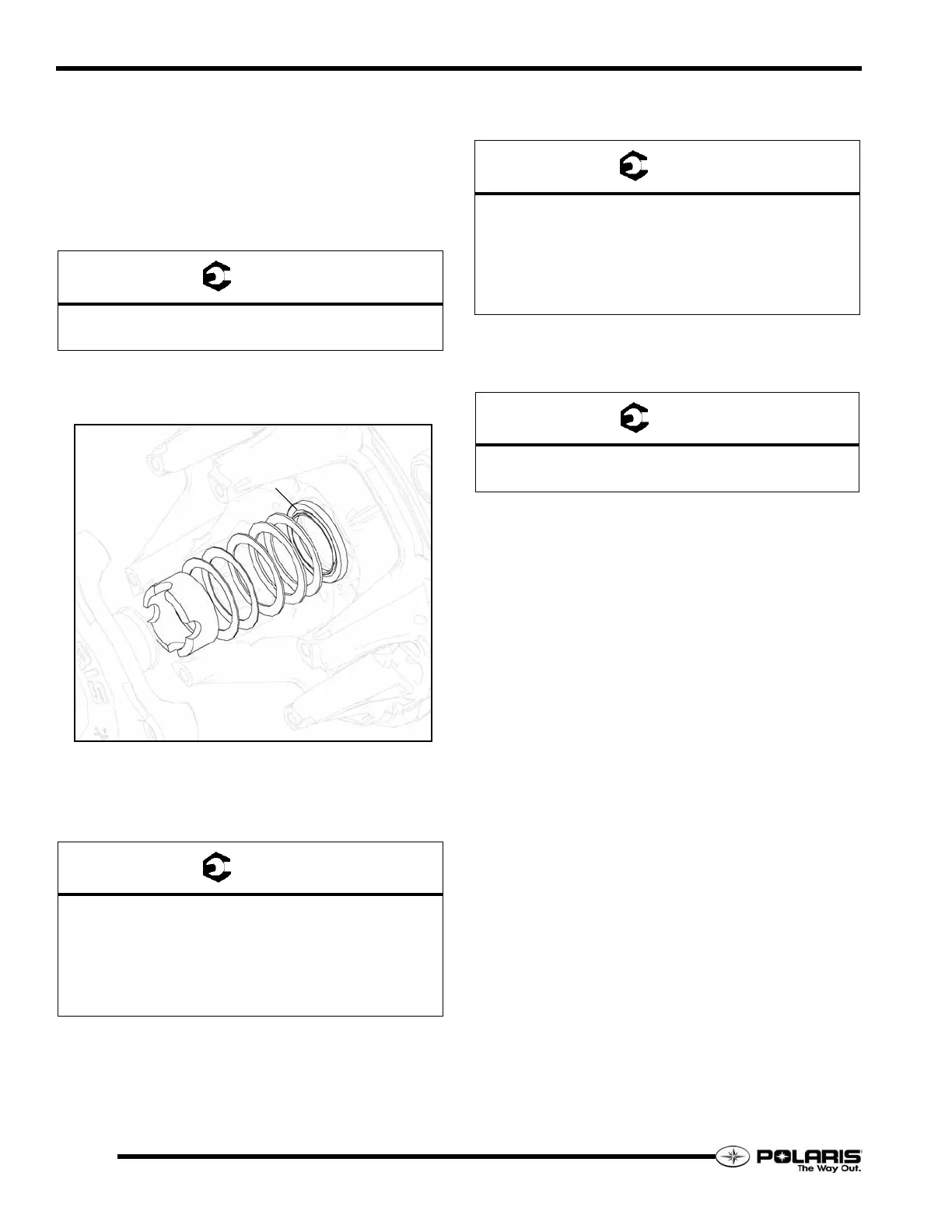
4. Place the moveable sheave onto the stationary sheave.
5. Place the same number of spacers on top of the stepped
spacer onto the shaft of the stationary sheave.
6. Thread the spider onto the stationary sheave shaft.
7. Index the spider. See “Spider Indexing” on page 7.17.
8. Using the spider tool (PN 2870341) torque to the spider to
specification.
9. Install the spider jam nut onto the shaft and torque to
specification.
10. Place the drive spring on the shaft.
11. Place the cover onto the clutch and torque the cover
fasteners to specification.
NOTE: Do not allow side loading or mis-alignment of
the cover or the bushing may become damaged.
= T
Weight Pin Torque
20 - 30 In.Lbs. (2.2 - 3.4 Nm)
= T
Spider Torque
All Except 800 CFI = 200 - 225 Ft.Lbs. (271 - 305 Nm)
Apply Loctite 620 to Threads.
800 CFI = 280 - 300 Ft.Lbs. (380 - 407 Nm)
Apply Loctite 242 to Threads.
JAM NUT
SPACERS
CLUTCH SPACER
= T
Spider Jam Nut Torque
All Except 800 CFI = 225 - 250 Ft.Lbs. (305 - 339 Nm)
Apply Loctite 620 to Threads.
800 CFI = 290 - 310 Ft.Lbs. (393 - 420 Nm) - Apply
Loctite 242 to Threads.
= T
Cover Fastener Torque
100 In.Lbs. (11 Nm)
 Loading...