5.20
Engine and Cooling Systems
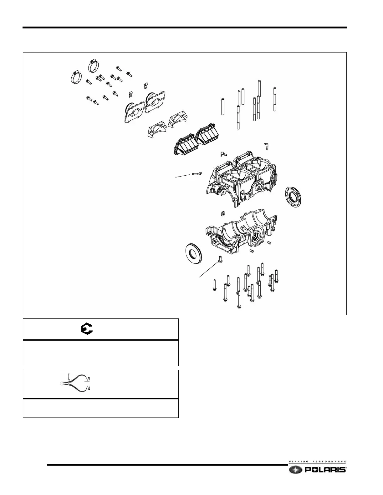
600 HO Carbureted Crankcase
Disassembly / Assembly Process
1. Remove the engine from the engine compartment.
2. Follow the process for removing the cylinder head,
cylinders, pistons, flywheel / recoil housing, and the water
/ oil pump.
3. Remove the intake boots, and reed assemblies. Discard any
seals or gaskets.
4. Remove the crankcase fasteners then carefully pry apart the
crankcase halves. Discard the PTO and MAG crankshaft
seals.
5. Clean the two crankcase mating surfaces with carburetor
cleaner and a gasket remover. Flush out the crankcase.
6. Reinstall the crankshaft back into the lower crankcase using
two new crankcase seals.
7. Apply a thin bead of Three Bond 1215 to the lower
crankcase mating surface. Install the upper crankcase.
8. Loosely install the crankcase fasteners, then torque to the
specifications at the beginning of the chapter. Use the
correct torque sequence when tightening the screws.
INTAKE BOOTS
REED STUFFERS
REED ASSEMBLIES
IMPULSE FITTING
OIL INJECTION CHECK VALVES
CRANKCASE
WATERPUMP BUSHING SCREW
DRAIN PLUGS
CYLINDER STUDS
A
B,C
= T
A = 9 Ft.Lbs. (12 Nm)
B = (M8) - 22 Ft.Lbs. (30 Nm) - Apply Loctite 242
C = (M6) - 9 Ft.Lbs. (12 Nm) - Apply Loctite 242
= In. / mm.
Long Studs Height (Exhaust side) = 3.66" (93mm)
Small Stud Height (Intake side) = 2.16
" (55mm)
 Loading...