11.8
Battery and Electrical Systems
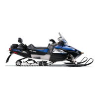
TPS Adjustment - Carbureted Models
NOTE: Always verify the engine idle speed is set at
engine operating temperature and the throttle cable
freeplay is set to 0.10″ - 0.30″.
1. Connect the TPS test tool to the TPS.
2. Slightly loosen the screws securing the TPS to carburetor
body.
3. Have an assistant hold the throttle flipper in the WOT
position.
4. Turn the TPS clockwise to decrease voltage
, or
counterclockwise to increase voltage.
5. Carefully tighten the TPS screws when the WOT Vdc is
4.00Vdc.
TPS Adjustment - CFI Models - Using Digital
Wrench
Either Digital Wrench or the TPS Test Tool can be used to see
the TPS return signal voltage, set the TPS baseline and set the
idle gap on CFI models.
To use Digital Wrench, follow these steps.
1. Click on the TOOLBOX icon.
2. Click on “TPS INITIALIZATION”
3. Follow the steps and procedures displayed on the screen.
TPS Baseline Adjustment - CFI Models
NOTE: The TPS baseline and idle speed
adjustments must be performed whenever the TPS
is moved or replaced.
1. Remove the drive belt, driven clutch, airbox, and adapter
plate.
2. If the TPS requires replacement, remove the throttle body
and replace the TPS.
NOTE: If only verifying the TPS voltage setting, the
throttle body can remain on the engine.
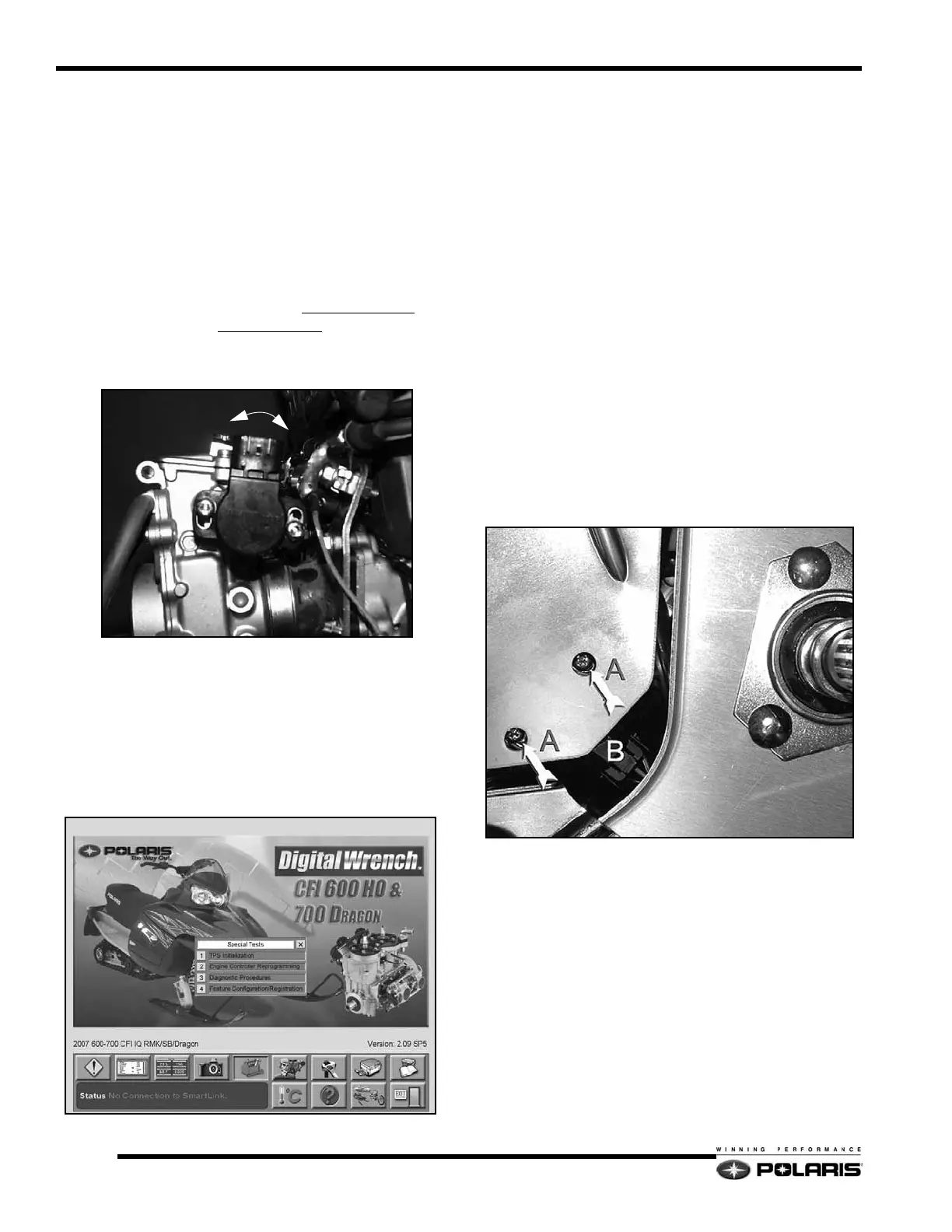
3. The TPS fasteners can be accessed through a set of access
holes in the TPS guard if adjustment is required.
4. Unplug the TPS connector (B), and connect the TPS test
tool.
NOTE: The guard may need to be “flexed” to align
the holes with the TPS fasteners.
• A = TPS Fasteners
• B = TPS Harness Connector
5. Remove the throttle cable barrel from the throttle flipper.

 Loading...