11.9
Battery and Electrical Systems
11
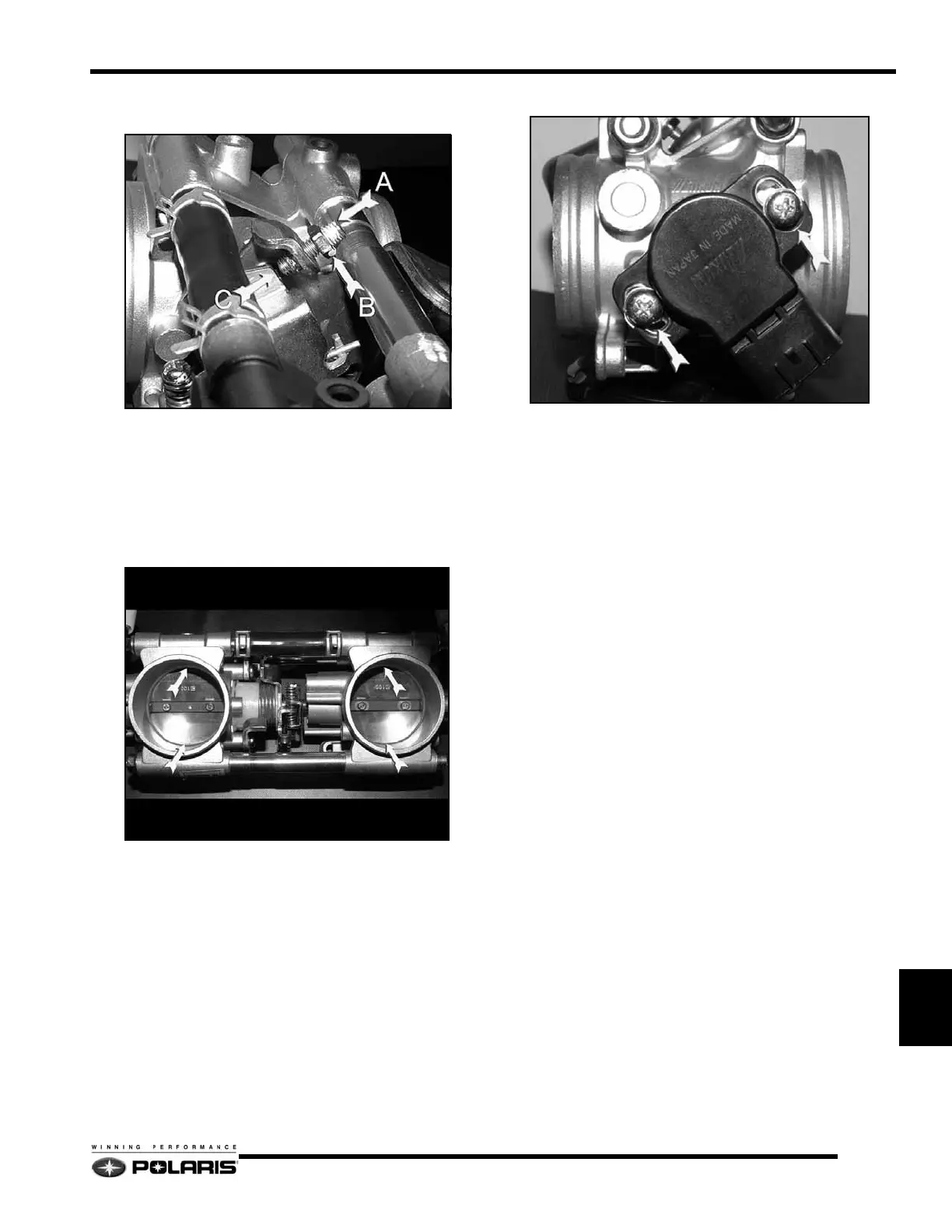
6. Loosen the idle speed screw until the screw no longer
touches the tab and the throttle plates are completely closed.
• A = Idle Speed Screw
•B = Lock Nut
• C = Throttle Stop
7. Open and close the throttle plates 2 to 3 times to ensure
plates are completely closed.
8. Using the TPS test tool, verify the TPS is set to 0.70 +/- 0.01
Vdc.
9. To adjust the TPS base-line, slightly loosen the screws, then
slowly turn the TPS clockwise or counter-clockwise to
adjust the voltage.
10. Carefully tighten the screws to 31 In.Lbs. (3.5 Nm) when
the voltage is 0.70 +/- 0.01 Vdc.
11. Open and close the throttle plate 2 - 3 times and verify the
voltage is still within specification.
 Loading...