8.2
Steering and Suspensions
OVERVIEW / SPECIFICATIONS
Inspection
When inspecting steering and suspension components for wear
or damage, always replace parts as necessary. Refer to the
assembly exploded views in this chapter for identification of
components and torque values of fasteners. Make notes of the
direction a bolt goes through a part, what type of nut is used in
an application, etc.
Some of the fasteners used in the IFS are special and cannot be
purchased at a hardware store. Always use genuine Polaris parts
and hardware when replacing front end components. Review
steering adjustment guidelines before making adjustments.
The following components must be inspected at this time.
• Tie rods and tie rod ends
• Torsion bar and bushings / linkage (where applicable)
• Handlebars and steering post assembly
• Spindles and bushings
• Skis and skags
• Pitman arms / Idler arms
• A-arms and bushings
• Shock absorbers, shock mounts, springs
• All related fasteners - check torque. Refer to steering
exploded views at the beginning of this section.
• Grease all fittings.
Always follow rod end engagement guidelines. Maximum
setup width must be checked whenever front suspension
components are adjusted or replaced.
Camber / Toe Specifications
Maximum width and camber measurements are to be taken with
the front end elevated and shocks at full extension.
Toe alignment is measured at ride height. This means that the
machine is on the ground and resting at normal ride height, not
full rebound. Measure at a point 10” (2.54cm) forward of the ski
mount bolt and 10” (2.54cm) behind the ski mount bolt,
preferably on the center line of the carbide skags.
Width is measured from the center of the spindles.
Camber measurement is taken from the top of the alignment bar
to the top of the ski mount hole in the spindle with the bushing
removed.
Springs
When the front suspension encounters a bump, the force of the
bump compresses the spring. If the bump force is 450 pounds,
a 100 #/in. spring will compress 4.5 inches. A 150 #/in. spring
will compress 3 inches. If the suspension had 4 inches of spring
travel, the 100 #/in. spring would bottom out, while the 150 #/
in. spring would have one inch of travel remaining.
• Free length - the length of a coil spring with no load
applied to the spring
• Installed length - the length of the spring between the
spring retainers. If the installed length of the spring is
less than the free length, it will be pre-loaded.
• Spring rate - the amount of force required to compress a
coil spring one inch. For example, if 150 pounds of
force are required to compress a spring 1 inch, the
spring rate would be 150 #/in.
• Straight rate spring - the spring requires the same
amount of force to compress the last one inch of travel
as the first one inch of travel. For example, if a 150 #/in.
spring requires 150 pounds of force to compress it one
inch, 300 pounds of force would compress it two
inches, 450 pounds of force would compress it three
inches, etc.
• Progressively wound spring - the rate of the spring
increases as it is compressed. For example, a 100/200 #/
in. rate spring requires 100 pounds of force to compress
the first one inch, but requires 200 additional pounds to
compress the last one inch.
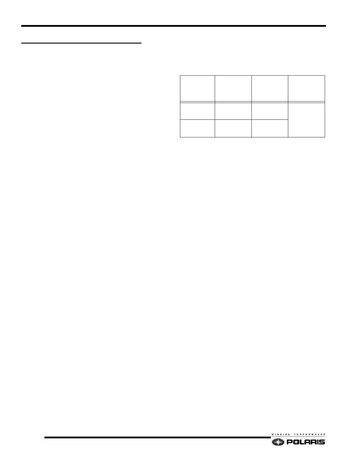
Camber & Toe Specifications
SUSPENSION
MAXIMUM SET
UP WIDTH in/
cm
(± .25in/.6cm)
CAMBER in/
mm
TOE OUT
(At ride height)
in/mm
IQ 42.5 42.5 / 108
2.25 ± .31
57 ± 7.9
0 -.12
0 -3.05
IQ RMK 38.67 / 98.2
2.17 ± .31
55 ± 7.9
 Loading...