7.19
PVT System
7
Team LWT Components
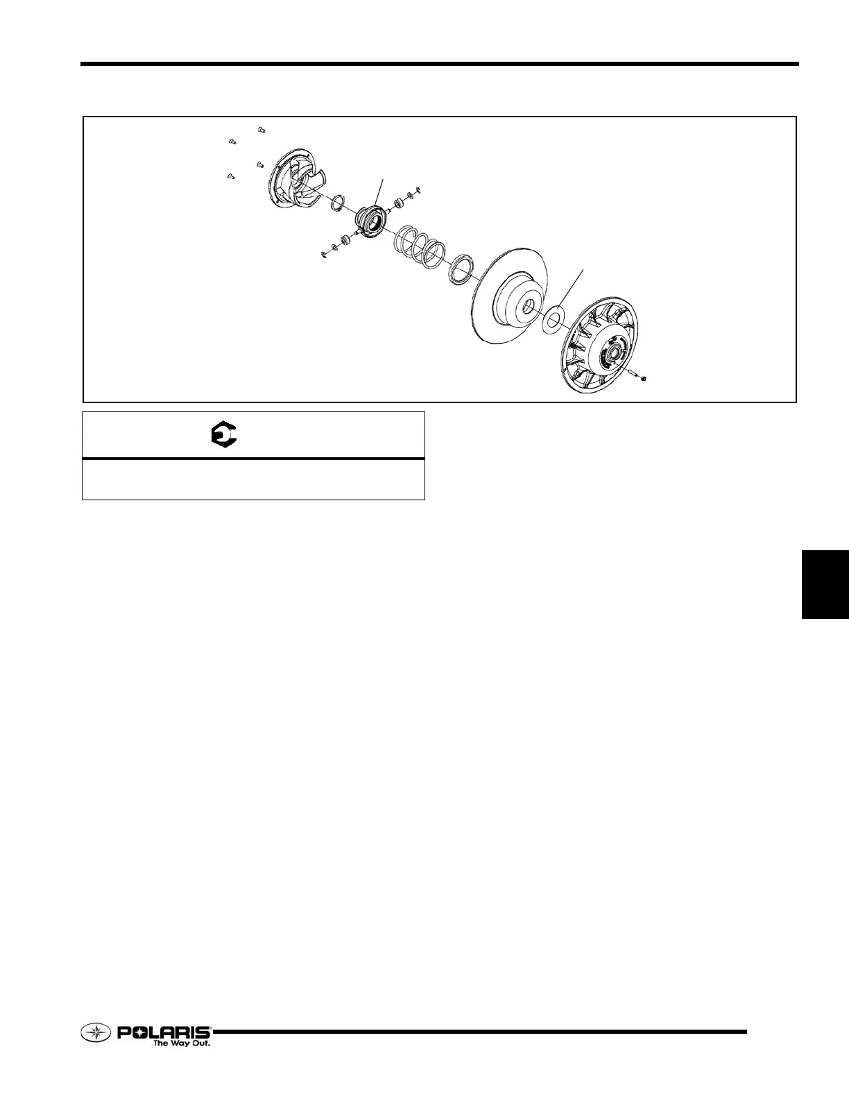
Disassembly and Assembly Process
1. Remove the screws from the helix, then carefully pry the
helix out of the moveable sheave.
2. Install the clutch in the clutch compressor fixture, PN
8700220. Install the extensions, PN PS-45909.
3. Wearing eye protection, carefully compress the roller
assembly to gain access to the snap ring. Remove the snap
ring.
4. Slowly release the fixture arm to remove the roller
assembly and spring. Disassembly the clutch sheaves.
5. Inspect the sheaves for abnormal wear. Clean sheave faces
with a Scotch Brite pad and a solution of warm, soapy
water.
6. Inspect spring, spring cup, spacer and rollers for wear and
replace as required.
7. To assemble the clutch, slide the components back on to the
stationary sheave shaft.
8. Align the notch in the roller assembly with row of double
splines on the shaft. Slowly compress the spring and roller
assembly down on to the shaft. Install the snap ring making
sure it is fully seated in the groove.
9. Install the helix by aligning the rollers with the ramps. Push
the helix down into the sheave while keeping the screws
holes aligned.
10. Install and torque helix fasteners to 60 - 80 in. lbs. (7 - 9
Nm).
HELIX
SNAP RING
SPRING
SPRING CUP
MOVEABLE SHEEVE
DEFLECTION SPACER
STATIONARY SHEEVE
BELT DEFLECTION SCREW
ROLLER ASSEMBLY
SCREWS
= T
Helix Fasteners = 60 - 80 In.Lbs. (7 - 9 Nm)
Driven Clutch Retaining Fastener = 17 Ft.Lbs. (23 Nm)

 Loading...