LTE-A Module Series
EG060V-EA Hardware Design
EG060V-EA_Hardware_Design 33 / 82
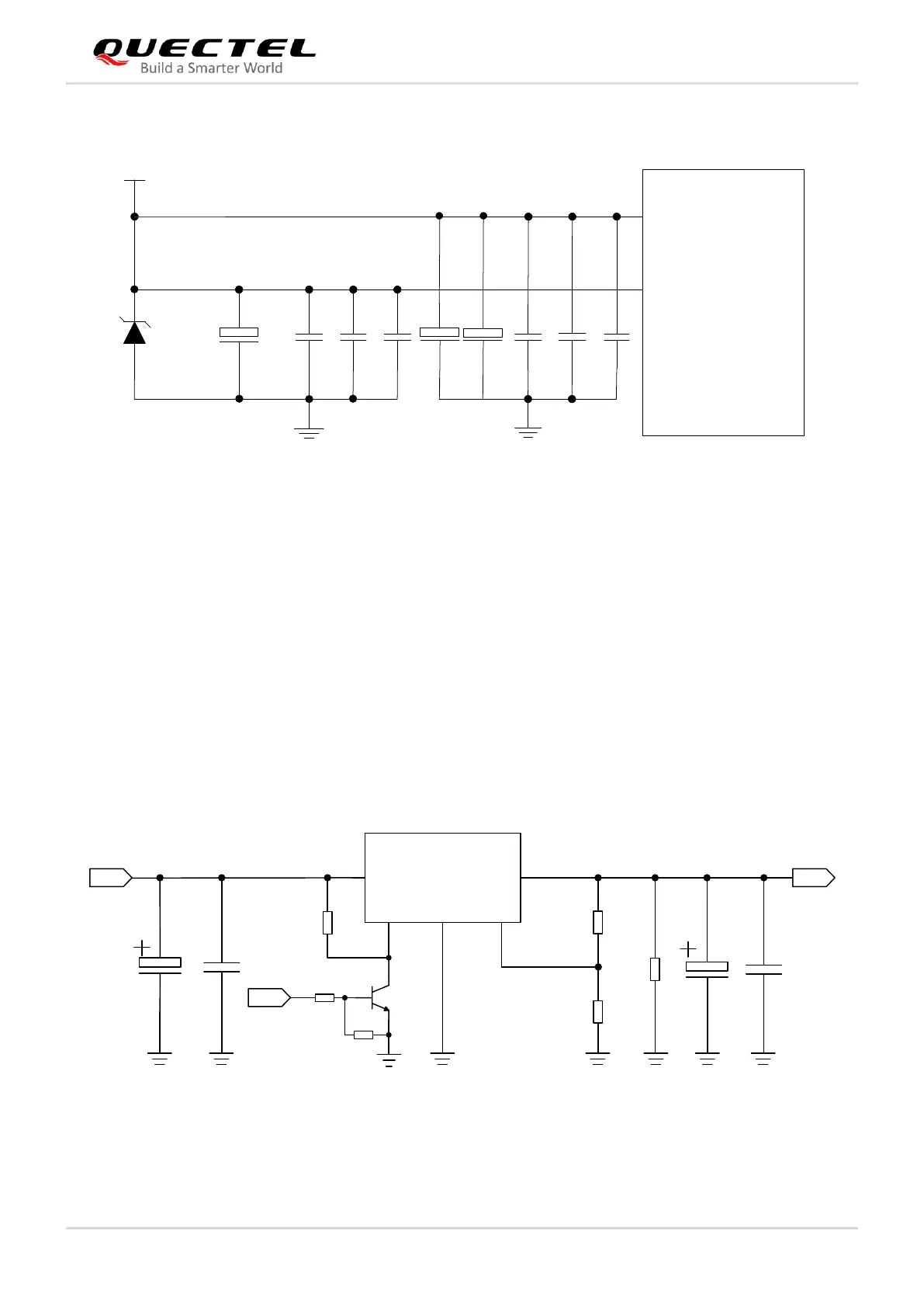
The following figure shows the star structure of the power supply.
Figure 9: Star Structure of Power Supply
3.6.3. Reference Design of Power Supply
Power design is critical as the performance of the module largely depends on the stability and suitability of
its power source. The power supply of EG060V-EA should be able to provide a sufficient current of 2 A
1)
at least. If the voltage drop between the input and output is not too high, it is suggested that an LDO
should be used while supplying power for the module. If there is a big voltage difference between the
input source and the desired output (VBAT), a buck converter is preferred.
The following figure shows a reference design for a +5 V input power source. The designed output of the
power supply is about 3.8 V and the maximum load current is 3 A.
 Loading...


