Raisecom
ISCOM2600G (A) Series Product Description
Raisecom Proprietary and Confidential
Copyright © Raisecom Technology Co., Ltd.
Optical interface on
local device
Direction of optical
signals
Optical interface on
peer device
6.1.2 Ethernet cable
Introduction
The Ethernet cable connects the Ethernet electrical interface and SFP electrical interface on
the ISCOM2600G series switch.
The Ethernet interface on the ISCOM2600G series switch is adaptive to straight-through
cable mode and crossover cable mode.
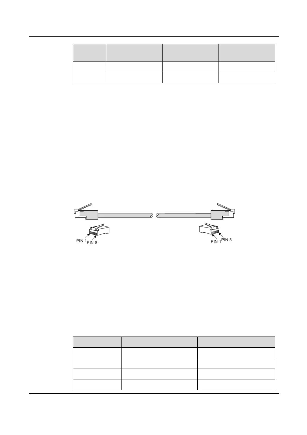
Appearance
Figure 6-2 shows the Ethernet cable.
Figure 6-2 Ethernet cable
Technical specifications
The Ethernet cables are divided into two types:
Straight-through cable: used to connect devices of different type, such as between a PC
and a switch, or between a switch and a router
Crossover cable: used to connect devices of the same type, such as between PCs,
between switches, between routers, or between a PC and a router (they are of the same
type)
Table 6-3 lists wiring of EIA/TIA 568A and EIA/TIA 568B standards.
Table 6-3 Wiring of EIA/TIA 568A and EIA/TIA 568B standards
 Loading...


