Raisecom
ISCOM5508-GP (A) Hardware Description
Raisecom Proprietary and Confidential
Copyright © Raisecom Technology Co., Ltd.
29
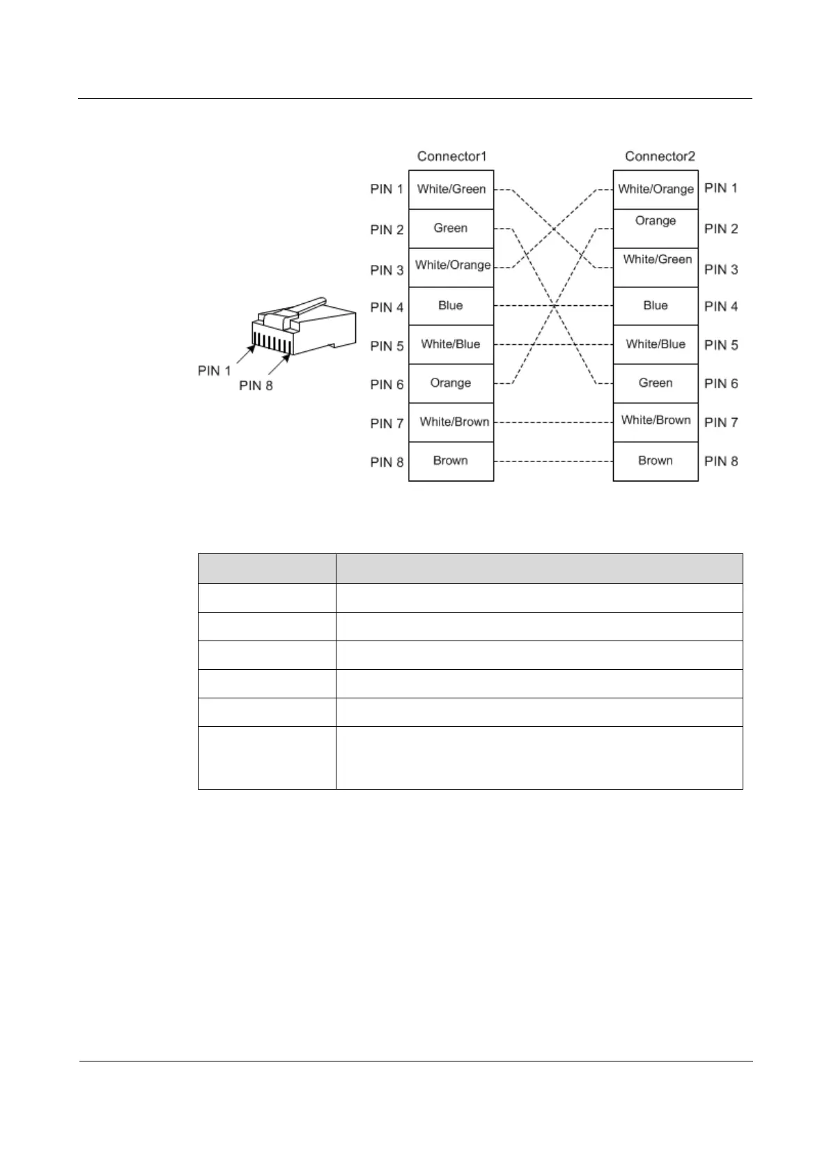
Figure 3-6 Crossover cable wiring
Table 3-6 lists technical specifications of the Ethernet cable.
Table 3-6 Technical specifications of the Ethernet cable
Item Description
Name CBL-ETH-RJ45/RJ45-D
Color Dark gray
Model UTP-3, UTP-5, or STP
Connector RJ45
Number of cores 8
Length
The letter D indicates the length, which can be customized. For
example, if the customer requires 2-meter cables, they are named
CBL-ETH-RJ45/RJ45-2m/RoHS.
3.3 Configuration cable
The configuration cable is used to connect the Console interface of the ISCOM5508-GP and
the RS-232 serial interface of the maintenance console, and transmit configuration data
signals. The maintenance console troubleshoots and maintains the ISCOM5508-GP through
the Console interface.
The configuration cable is a 4-core UTP cable. Connectors at the two ends are:
RJ45 connector: connect the Console interface of the ISCOM5508-GP.
DB9 female connector: connect the RS-232 serial interface of the maintenance console.
 Loading...