Raisecom
ISCOM5508-GP (A) Hardware Description
Raisecom Proprietary and Confidential
Copyright © Raisecom Technology Co., Ltd.
34
3.6 Ground cable
Connecting the ground cable properly is an important guarantee for lightning
protection, anti-electric shock, and anti-interference. The ISCOM5508-GP must be
connected to the ground cable correctly during installation, which helps avoid
personal injury and equipment damage.
3.6.1 Introduction
The ground cable is used to ground the ISCOM5508-GP.
3.6.2 Appearance
The ground cable is composed of the ground terminal and conductive wire. In general, ground
terminals are OT bare-pressure terminals; and the conductive wire is a
yellow/green copper
soft flame-retardant conducting wire.
Figure 3-12 and Figure 3-13 shows the ground cable and OT terminal respectively.
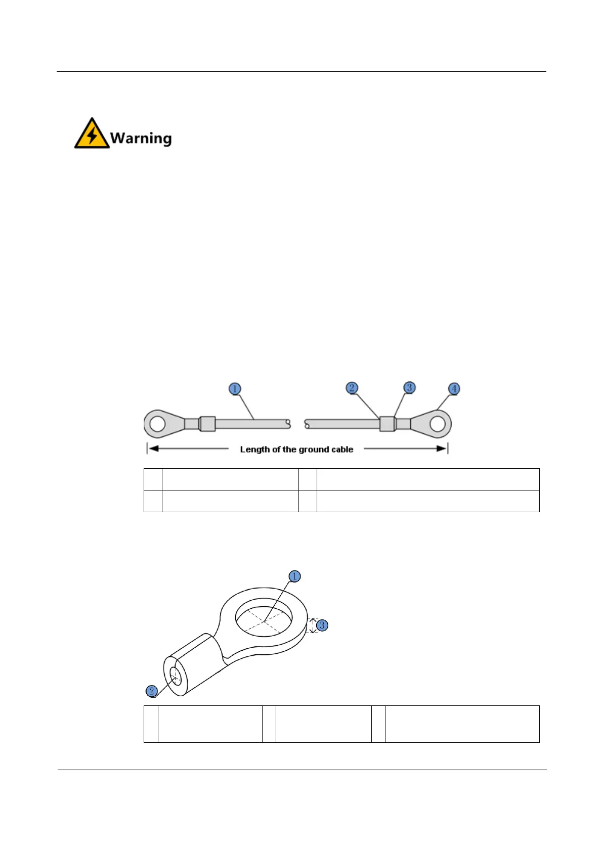
Figure 3-12 Ground cable
1 Conducting wire 2 Stripped end (connected to the OT terminal)
3 Insulating sheath 4 OT terminal
Figure 3-13 OT terminal
1
Inner diameter of
soldering lug
2
Inner diameter of
sheath
3
Thickness of soldering terminal
 Loading...