Raisecom
ISCOM5508-GP (A) Hardware Description
Raisecom Proprietary and Confidential
Copyright © Raisecom Technology Co., Ltd.
31
Table 3-8 PINs of the RJ45 Ethernet interface
PIN Function PIN Function
PIN 1 NC PIN 5 GND
PIN 2 NC PIN 6 TxD
PIN 3 RxD PIN 7 NC
PIN 4 GND PIN 8 NC
3.4 DC power cable
3.4.1 Introduction
The DC power cable supplies -48 VDC power from the power souring equipment to the
power interface on the RPD0601 module of the ISCOM5508-GP, and then transmits power to
the entire device.
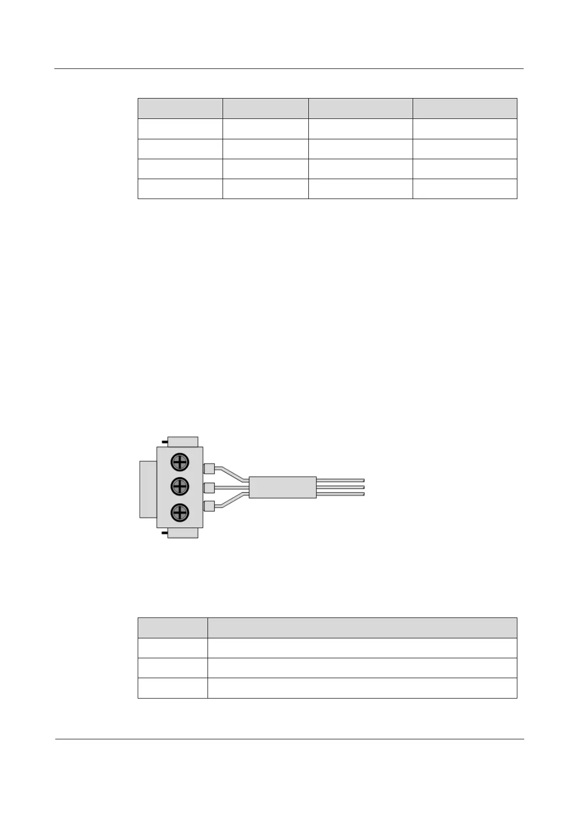
3.4.2 Appearance
The DC power cable is composed of the DC power connector and coaxial cable, as shown in
Figure 3-9.
Figure 3-9 DC power cable
3.4.3 Technical specifications
Table 3-9 lists technical specifications of the DC power cable.
Table 3-9 Technical specifications of the DC power cable
Item Description
Name POL-DC-unstripped/stripped-1.0mm
2
-D/RoHS
Connector DC connector-3Pin-head/UL/RoHS
Model Copper core multi-strand power cable (1.0 mm
2
)
 Loading...