32
TYPE 100/300 Operation and Installation Handbook
bar. Minor adjustments can be made by loosening the 3 securing
screws and rotating the transducer body.
2. The tiller pin must be positioned within the limits shown. Ideally,
dimension ‘A’ should be 140mm (5.5in). However, changes within the
given limits will not degrade the autopilot performance, but will slightly
alter the scaling of the rudder angle display on the control unit. The
tiller pin is secured to the tiller arm using the self tapping screws
provided.
3. Cut the threaded rod to length and screw on the lock nuts ‘Y’and the
ball pin sockets - the sockets can then be pressed onto the pins. Move
the rudder from side to side to ensure the linkage is free from any
obstruction at all rudder angles.
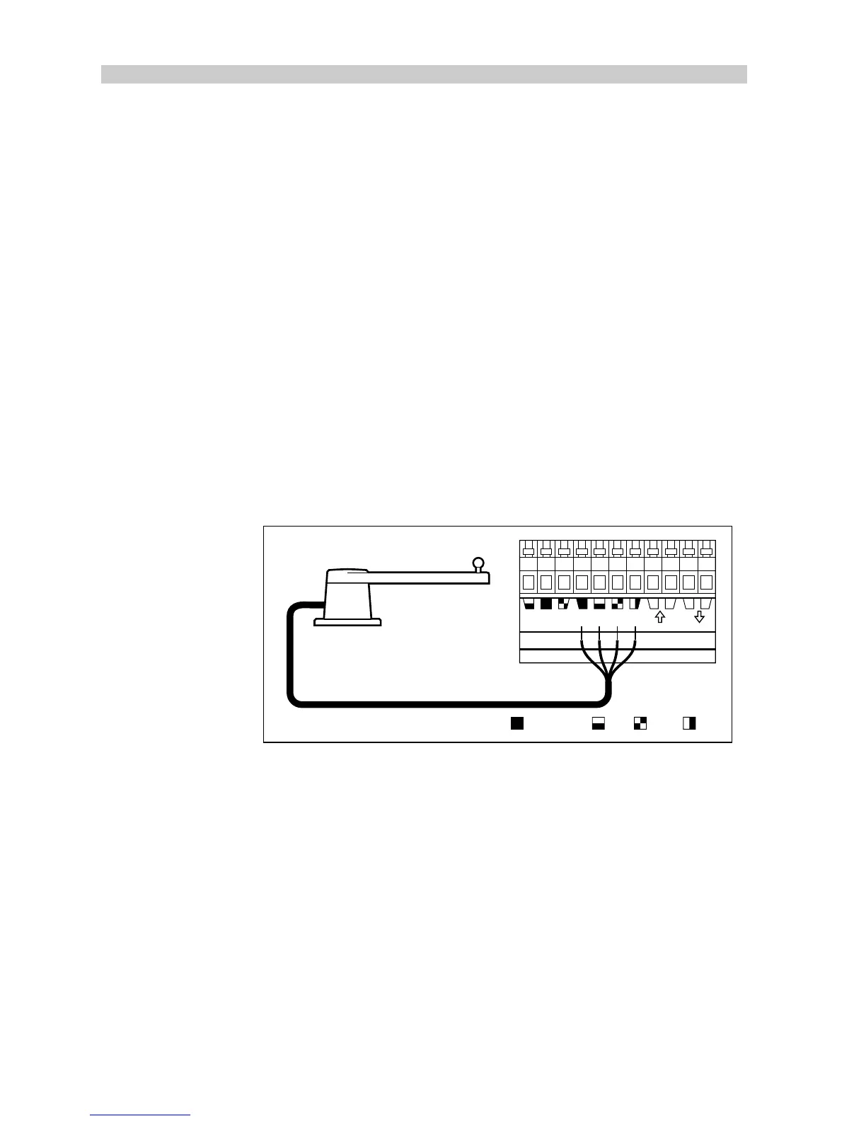
Cabling
1. Run the rudder reference cable back to the course computer.
2. Connect to the rudder reference terminals on the course computer.
GYRO 2 RUDDER REF. NMEA
+–+–
D894-1
Grey (screen) BlueRed Green
Note:
A 10m (30ft) extension cable is available for larger installations
(part no. D173).
 Loading...