34
TYPE 100/300 Operation and Installation Handbook
10. Position the linear feedback transducer (5) on top of the spacers (4)
so that the threaded end of the shaft passes through the
U-bracket (3).
Note:
The linear feedback transducer should, under normal circum-
stances, be assembled with the shaft (9) pointing towards starboard.
However, if it is not possible to orientate the unit in this way, port installa-
tion is possible providing the red and green wires are reversed at the
course computer.
11. With the adjustment screw and barrel aligned with the spacers, close
the hose clamps (6) around the linear feedback transducer (5) and the
‘bullhorn’ ram (1).
12. Tighten the ‘bullhorn’ bolt to retain the U-bracket (3).
13. Fit and tighten the nut (7) and washer (8) to the shaft of the linear
feedback transducer (5).
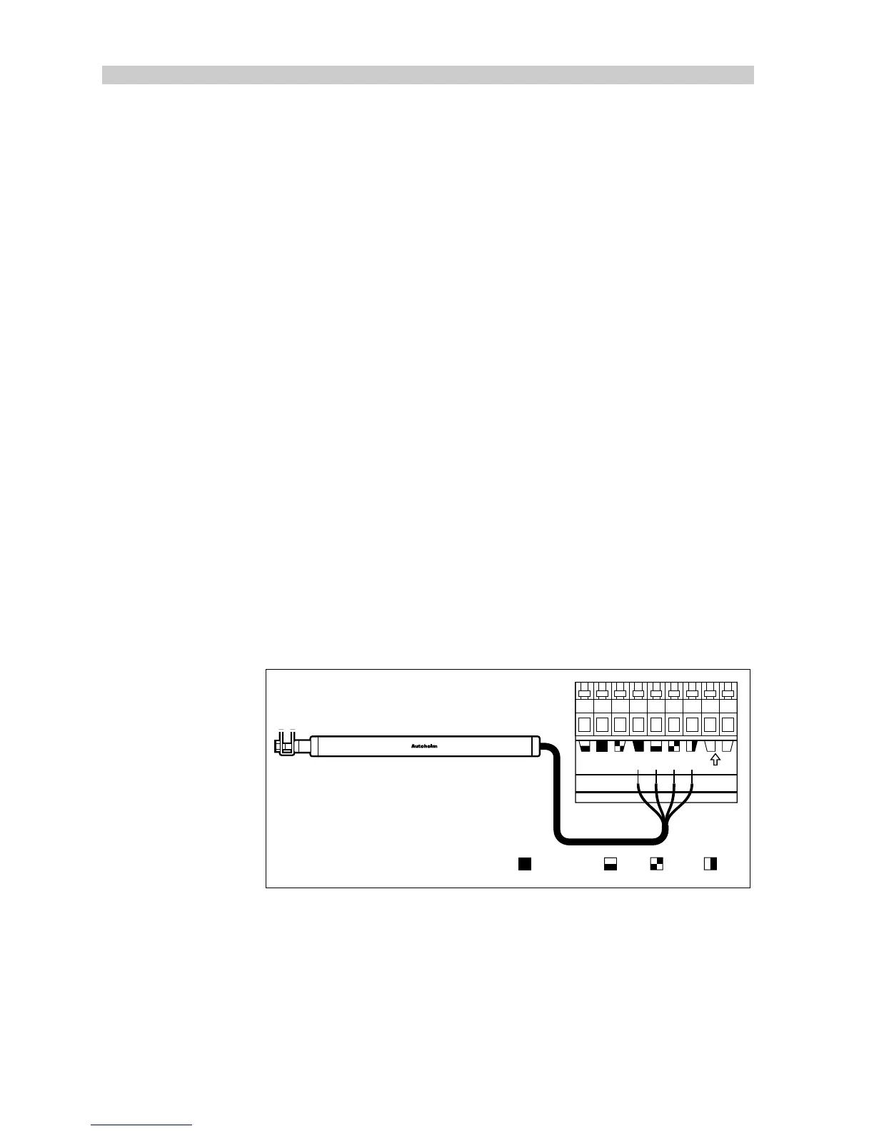
Cabling
1. Run the linear feedback transducer cable back to the course
computer.
2. Connect to the course computer rudder reference terminals.
Note:
To allow for movement of the bullhorn, leave a loop of cable at the
end of the Linear Feedback Transducer.
GYRO 2 RUDDER REF. NM
+–
D895-1
TM
Grey (screen) BlueRed Green
 Loading...