Home
Raymarine
Autopilot System
EVOLUTION ACU-100
Raymarine EVOLUTION ACU-100 User Manual
5
of 1
of 1 rating
Go to English
150 pages
Give review
Manual
Specs
To Next Page
To Next Page
To Previous Page
To Previous Page
Loading...
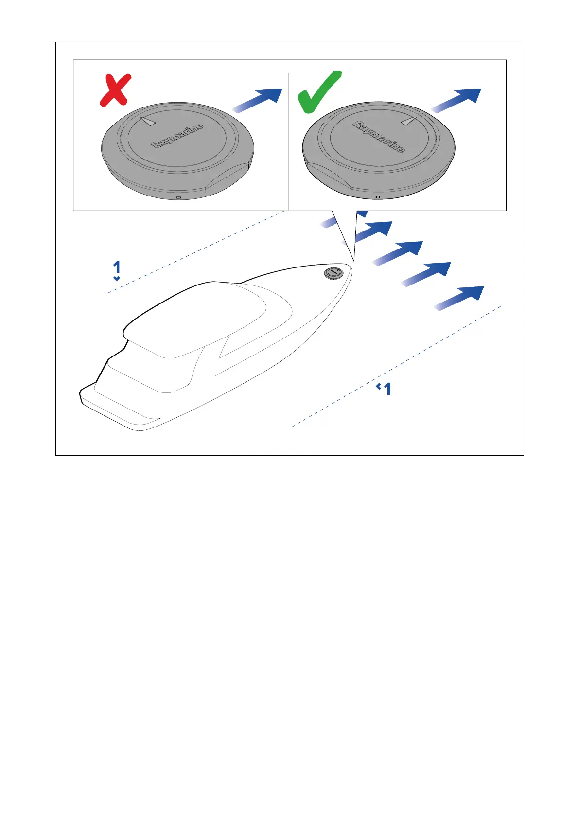
1.船舶の縦軸
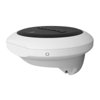
7.4 設置場所の要件 - ACU
設置場所は、以下の要件を考慮しなければならない:
-
ACU-200, ACU-300, ACU-400 - デッキ下の乾燥した場所に設置する。
-
ACU-100, ACU-150 - デッキの上または下に設置。
-
ユニットは垂直面に設置する。
-
本機は、バッテリーのできるだけ近くに設置する必要があります。
-
本機に荷重や力がかからない場所を選んでください。
-
熱源や、燃料蒸気などの可燃性の危険源から離して取り付けてください。
-
本機は、診断 LED が見える場所に取り付けてください。
Location
requirements
43
42
44
Table of Contents
Chapter 1 Important information
9
Water ingress
10
Disclaimer
10
Suppression ferrites
10
Connections to other equipment
10
Declaration of Conformity
10
Declaration of Conformity
11
Declaration of Conformity
11
Declaration of Conformity
11
Declaration of Conformity
11
Declaration of Conformity
11
Product disposal
11
Warranty registration
12
IMO and SOLAS
12
Technical accuracy
12
Chapter 2 Document information
13
2.1 Handbook information
14
Applicable products
14
Product documentation
14
Document illustrations
16
Chapter 3 Product and system overview
17
3.1 Product overview
18
Required additional components
19
SeaTalkng®
19
Multiple data sources (MDS)
19
System examples
21
Compatible autopilot controllers
26
Compatible autopilot controllers - MFDs
27
Compatible drive units
28
Software updates
30
Chapter 4 Parts supplied
31
4.1 Parts supplied — EV-1 and EV-2
32
4.2 Parts supplied — ACU-100, ACU-150
33
4.3 Parts supplied — ACU-200, ACU-300, ACU-400
33
Chapter 5 Product dimensions
35
5.1 Dimensions — EV–1 and EV–2
36
5.2 Dimensions — ACU-100, ACU-150
37
5.3 Dimensions — ACU-200, ACU-300, ACU-400
38
Chapter 6 Installation sequence
39
6.1 Installation checklist
40
Schematic diagram
40
Chapter 7 Location requirements
41
7.1 Warnings and cautions
42
7.2 Potential ignition source
42
7.3 Location requirements — EV–1 and EV–2
42
7.4 Location requirements — ACU
43
7.5 Compass safe distance
44
7.6 EMC installation guidelines
44
Chapter 8 Installation
45
8.1 EV-1 Installation
46
Surface mounting the EV-1
46
Surface mounting using the Riser
48
Bracket mounting the EV-1
50
Releasing the unit from the bracket
52
8.2 ACU Installation
53
Mounting the ACU-100, ACU-150
53
Mounting the ACU-200, ACU-300, ACU-400
56
8.3 Drive unit installation
57
Autopilot drive unit documentation
57
Chapter 9 EV-1 connections
59
9.1 General cabling guidance
60
Cable types and length
60
Cable routing
60
Strain relief
60
Cable shielding
60
9.2 Connections overview — EV-1 and EV-2
61
9.3 Connecting SeaTalkng® cables
61
9.4 Power connection — EV-1
62
9.5 SeaTalkng® power connection point
62
In-line fuse and thermal breaker ratings
63
SeaTalkng® system loading
63
9.6 Power distribution — SeaTalkng®
63
Sharing a breaker
66
Chapter 10 ACU–100 / ACU–150 connections
69
10.1 ACU-100, ACU-150 connections
70
Connections overview — ACU-100, ACU-150
70
Making connections
70
Example: Evolution recommended system ACU-100, ACU-150
71
Power connection — ACU-100, ACU-150
72
Grounding — Dedicated drain wire required
73
Power distribution — ACU
74
Power and drive cables
77
Drive (motor) connection — ACU-100, ACU-150
78
SeaTalkng® connection — ACU-100, ACU-150
80
Rudder angle reference sensor connection
81
Chapter 11 ACU-200, ACU-300, ACU-400 connections
83
11.1 ACU-200, ACU-300, ACU-400 connections
84
Connections overview — ACU-200
84
Connections overview — ACU-300
84
Connections overview — ACU-400
85
Making connections
85
Example: Evolution recommended system ACU-200, ACU-300, ACU-400
86
Power connection — ACU-200, ACU-300, ACU-400
87
Grounding — Dedicated drain wire required
88
Power distribution — ACU
89
Power and drive cables
92
Motor (drive) and clutch connection — ACU-200 and ACU-400
93
Solenoid (drive) and bypass valve connection - ACU-300
96
VMU adapter connection — ACU-400
98
SeaTalkng® connection — ACU-200, ACU-300, ACU-400
99
Sleep switch connection — ACU-200, ACU-300, ACU-400
100
Rudder angle reference sensor connection
100
Chapter 12 Pilot controller connections
103
12.1 SeaTalkng pilot controller connection
104
12.2 SeaTalk® pilot controller connection
105
Chapter 13 System checks and troubleshooting
107
13.1 Post-installation checks
108
13.2 Error messages (Troubleshooting)
109
13.3 Autopilot system setup
112
13.4 Alarms
113
13.5 LED indications — EV-1
115
13.6 LED indications — ACU
116
13.7 Rudder damping levels and deadband angles
117
Rudder Damping level adjustments
117
Chapter 14 Operation
119
14.1 Evolution autopilot operation instructions
120
Autopilot controller documentation
120
Chapter 15 Maintenance
121
15.1 Service and maintenance
122
15.2 Routine equipment checks
122
15.3 Product cleaning
122
Chapter 16 Technical support
123
16.1 Raymarine product support and servicing
124
Viewing product information
125
16.2 Learning resources
125
Chapter 17 Technical specification
127
17.1 Technical specification — EV-1 and EV-2
128
17.2 Technical specification — ACU-100, ACU-150
129
17.3 Technical specification — ACU-200, ACU-300, ACU-400
130
Chapter 18 Spares and accessories
133
18.1 Accessories and spare parts
134
18.2 SeaTalkng® cables and accessories
135
Appendix A NMEA 2000 sentences (PGNs) — EV-1 and EV-2
141
Appendix B NMEA 2000 sentences (PGNs) — ACU
143
Blank Page
148
Blank Page
149
Other manuals for Raymarine EVOLUTION ACU-100
Installation Instructions
142 pages
5
Based on 1 rating
Ask a question
Give review
Questions and Answers:
Need help?
Do you have a question about the Raymarine EVOLUTION ACU-100 and is the answer not in the manual?
Ask a question
Raymarine EVOLUTION ACU-100 Specifications
General
Brand
Raymarine
Model
EVOLUTION ACU-100
Category
Autopilot System
Language
English
Related product manuals
Raymarine EVOLUTION ACU-150
150 pages
Raymarine EVOLUTION ACU-400
150 pages
Raymarine Evolution EV-1
150 pages
Raymarine Evolution EV-2
96 pages
Raymarine E70096
142 pages
Raymarine E70099
142 pages
Raymarine E12207
42 pages
Raymarine Autohelm 4000
13 pages
Raymarine Autohelm 6000
38 pages
Raymarine Autohelm ST6000
32 pages
Raymarine Pathfinder GyroPlus 2
40 pages
ST1000 Plus Tiller Pilots
76 pages