9. Interrupts
puorG92/C61M
page 74
854fo7002,03.raM21.1.veR
2110-1010B90JER
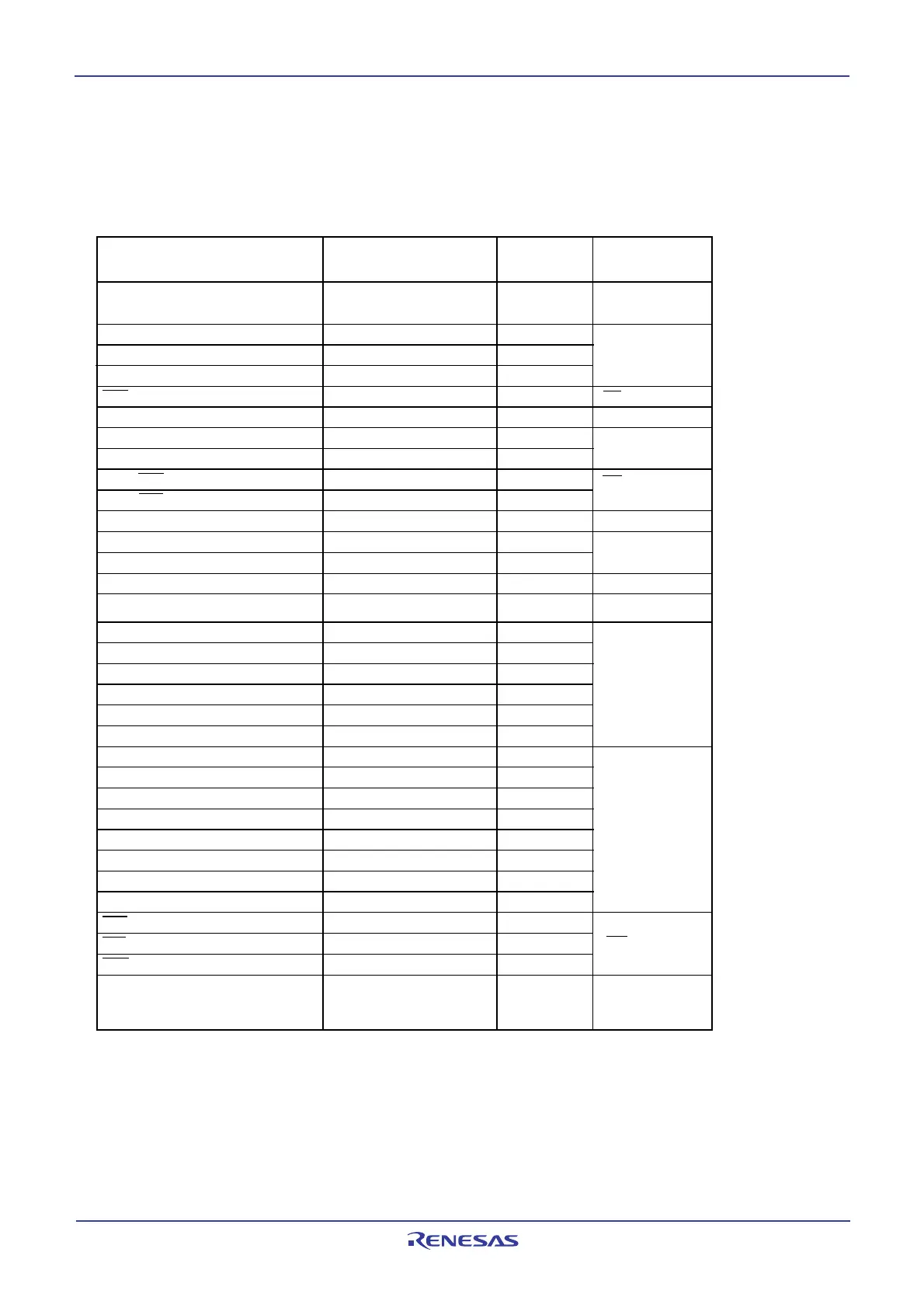
Table 9.2 Relocatable Vector Tables
9.2.2 Relocatable Vector Tables
The 256 bytes beginning with the start address set in the INTB register comprise a reloacatable vector
table area. Table 9.2 lists the relocatable vector tables. Setting an even address in the INTB register
results in the interrupt sequence being executed faster than in the case of odd addresses.
Software interrupt
number
Reference
Vector address
(1)
Address (L) to address (H)
0
11
12
13
14
17
18
19
20
21
22
23
24
25
26
27
28
29
30
31
32
63
to
10
15
16
5
6
7
8
4
9
1
Interrupt source
BRK instruction
(2)
INT3
SI/O3, INT4
(5)
SI/O4, INT5
(5)
IC/OC interrupt 1, I
2
C bus interface
(4)
IC/OC interrupt 0
DMA0
DMA1
A/D, Key input interrupt
(7)
UART0 transmit
UART0 receive
UART1 transmit
UART1 receive
Timer A0
Timer A1
Timer A2
Timer A3
Timer A4
Timer B0
Timer B1
Timer B2
INT0
INT1
INT2
Software interrupt
(2)
UART 2 bus collision detection
(6)
UART2 transmit, NACK2
(8)
UART2 receive, ACK2
(8)
IC/OC base timer, S
CL/SDA
(4)
M16C/60, M16C/20
series software
manual
INT interrupt
Timer S
Multi-Master I
2
C bus
interface
CAN module
INT interrupt
Serial I/O
DMAC
A/D convertor,
Key input interrupt
Serial I/O
Timer
INT interrupt
M16C/60, M16C/20
series software
manual
CAN0 wakeup
(3)
+0 to +3 (0000
16
to 0003
16
)
+44 to +47 (002C
16
to 002F
16
)
+48 to +51 (0030
16
to 0033
16
)
+52 to +55 (0034
16
to 0037
16
)
+56 to +59 (0038
16
to 003B
16
)
+68 to +71 (0044
16
to 0047
16
)
+72 to +75 (0048
16
to 004B
16
)
+76 to +79 (004C
16
to 004F
16
)
+80 to +83 (0050
16
to 0053
16
)
+84 to +87 (0054
16
to 0057
16
)
+88 to +91 (0058
16
to 005B
16
)
+92 to +95 (005C
16
to 005F
16
)
+96 to +99 (0060
16
to 0063
16
)
+100 to +103 (0064
16
to 0067
16
)
+104 to +107 (0068
16
to 006B
16
)
+108 to +111 (006C
16
to 006F
16
)
+112 to +115 (0070
16
to 0073
16
)
+116 to +119 (0074
16
to 0077
16
)
+120 to +123 (0078
16
to 007B
16
)
+124 to +127 (007C
16
to 007F
16
)
+128 to +131 (0080
16
to 0083
16
)
+252 to +255 (00FC
16
to 00FF
16
)
+40 to +43 (0028
16
to 002B
16
)
+60 to +63 (003C
16
to 003F
16
)
+64 to +67 (0040
16
to 0043
16
)
+20 to +23 (0014
16
to 0017
16
)
+24 to +27 (0018
16
to 001B
16
)
+28 to +31 (001C
16
to 001F
16
)
+32 to +35 (0020
16
to 0023
16
)
+16 to +19 (0010
16
to 0013
16
)
+36 to +39 (0024
16
to 0027
16
)
to
2
3
+4 to +7 (0004
16
to 0007
16
)
+8 to +11 (0008
16
to 000B
16
)
+12 to +15 (000C
16
to 000F
16
)
CAN0 receive completion
CAN0 transmit completion
Timer S
Serial I/O
CAN0 state, error CAN module
NOTES:
1. Address relative to address in INTB.
2. These interrupts cannot be disabled using the I flag.
3. Set the IFSR22 bit in the IFSR register to 0.
4. Use bits IFSR26 and IFSR27 in the IFSR2A register to select.
5. Use bits IFSR6 and IFSR7 in the IFSR register to select.
6. Bus collision detection: In IEBus mode, this bus collision detection constitutes the cause of an interrupt. In I
2
C bus
mode, however, a start condition or a stop condition detection constitutes the cause of an interrupt.
7. Use the IFSR21 bit in the IFSR2A register to select.
8. During I
2
C bus mode, NACK and ACK interrupts comprise the interrupt source.
 Loading...


