16. MULTI-MASTER I
2
C bus INTERFACE
puorG92/C61M
page 282
854fo7002,03.raM21.1.veR
2110-1010B90JER
16.13 Address Data Communication
This section describes data transmit control when a master transferes data or a slave receives data in 7-bit
address format. Figure 16.20 (1) shows a master transmit format.
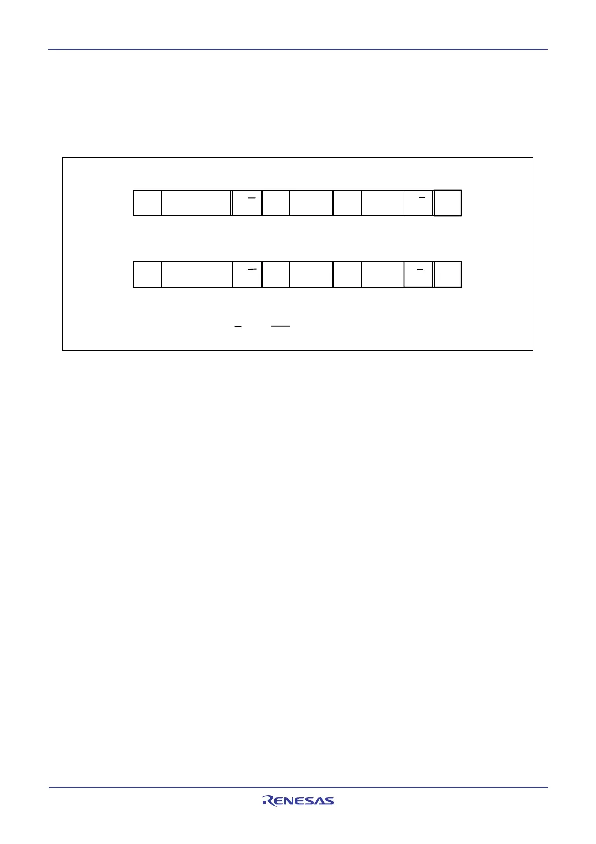
Figure 16.20 Address data communication format
16.13.1 Example of Master Transmit
For example, a master transmits data as shown below when following conditions are met: standard clock
mode, SCL clock frequency of 100kHz and ACK clock added.
1) Set s slave address to the 7 high-order bits in the S0D0 register
2) Set 8516 to the S20 register, 0002 to bits ICK4 to ICK2 in the S4D0 register and 0016 to the S3D0
registe to generate an ACK clock and set SCL clock frequency t 100 kHz (f1=8MHz, fIIC=f1)
3) Set 0016 to the S10 register to reset transmit/receive
4) Set 0816 to the S1D0 register to enable data communication
5) Confirm whether the bus is free by BB flag setting in the S10 register
6) Set E016 to the S10 register to enter START condition standby mode
7) Set the destination address in 7 high-order bits and 0 to a least significant bit in the S00 register to
generate START condition. At this time, the first byte consisting of SCL and ACK clock are auto-
matically generated
8) Set a transmit data to the S00 register. At this time, SCL and an ACK clock are automatically
generated
9) When transmitting more than 1-byte control data, repeat the above step 8).
10) Set C016 in the S10 register to enter STOP condition standby mode if ACK is not returned from the
slave receiver or if the transmit is completed
11) Write dummy data to the S00 regiser to generate STOP condition
1 - 8 bits
S: START condition P: STOP condition
A: ACK bit R/W: Read/Write bit
S S
l
a
v
e
a
d
d
r
e
s
s R/W A
a
t
a
AA/A P
SR/W A A
P
1
a
t
a
a
t
a
a
t
a
S
l
a
v
e
a
d
d
r
e
s
s
7 bits
(1) A master transmit device transmits data to a receive device
(2) A master receive device receives data from a transmit device
1 - 8 bits
1 - 8 bits 07 bits 1 - 8 bits
 Loading...


