17. CAN Module
puorG92/C61M
page 311
854fo7002,03.raM21.1.veR
2110-1010B90JER
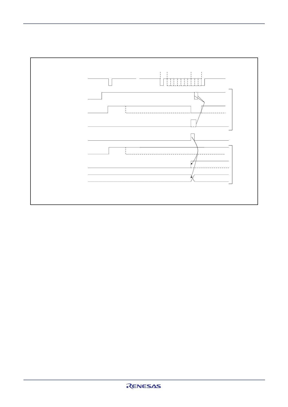
17.10.2 Transmission
Figure 17.26 shows the timing of the transmit sequence.
CTx
TrmReq bit
TrmActive bit
CAN0 Successful
Transmission Interrupt
TrmState bit
TrmSucc bit
MBOX bit
SentData bit
SOF
SOF
Transmission slot No.
C0MCTLj register
C0STR register
EOF IFS
(1)
(2)
(2)
(1)
(1)
(3)
(4)
(3)
(3)
= 0 to 15
ACK
Figure 17.26 Timing of Transmit Sequence
(1) If the TrmReq bit in the C0MCTLj register (j = 0 to 15) is set to 1 (Transmission slot) in the bus idle
state, the TrmActive bit in the C0MCTLj register and the TrmState bit in the C0STR register are set to
1 (Transmitting/Transmitter), and CAN module starts the transmission.
(2) If the arbitration is lost after the CAN module starts the transmission, the TrmActive and TrmState bits
are set to 0.
(3) If the transmission has been successful without lost in arbitration, the SentData bit in the C0MCTLj
register is set to 1 (Transmission is successfully completed) and TrmActive bit in the C0MCTLj register
is set to 0 (Waiting for bus idle or completion of arbitration). And when the interrupt enable bits in the
C0ICR register = 1 (Interrupt enabled), CAN0 successful transmission interrupt request is generated
and the MBOX (the slot number which transmitted the message) and TrmSucc bit in the C0STR
register are changed.
(4) When starting the next transmission, set bits SentData and TrmReq to 0. And set the TrmReq bit to
1 after checking that bits SentData and TrmReq are set to 0.
 Loading...


