17. CAN Module
puorG92/C61M
page 307
854fo7002,03.raM21.1.veR
2110-1010B90JER
17.6 BasicCAN Mode
When the BasicCAN bit in the C0CTLR register is set to 1 (Basic CAN mode enabled), slots 14 and 15
correspond to Basic CAN mode. During normal operations, individual slots can select either data frame or
remote frame by CPU setting. However, in Basic CAN mode, both frames can be selected.
When slots 14 and 15 are defined as reception slots in Basic CAN mode, received messages are stored in
slots 14 and 15 alternately.
The received message data format can be determined by the RemActive bit in the C0MCTLj register (j = 0
to 15).
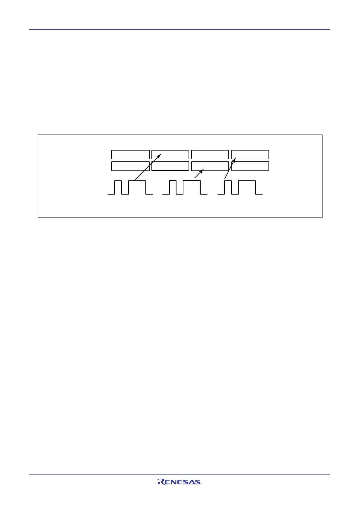
Figure 17.24 shows the operation of slots 14 and 15 in Basic CAN mode.
Figure 17.24 Operation of Slots 14 and 15 in Basic CAN Mode
When using Basic CAN mode, note the following points.
(1) Setting of Basic CAN mode has to be done in CAN reset/initialization mode.
(2) Select the same ID for slots 14 and 15. Also, setting of the C0LMAR and C0LMBR register has to be
the same.
(3) Define slots 14 and 15 as reception slot only.
(4) There is no protection available against message overwrite. A message can be overwritten by a new
message.
(5) Slots 0 to 13 can be used in the same way as in normal CAN operating mode.
Slot 14
Slot 15
Msg n Msg n+1 Msg n+2
Empty
Locked (empty) Locked (empty)
Msg n
Locked
Msg n + 1
Msg n+2
(Msg n lost)
Locked (Msg n+1
)
(Msg n)
 Loading...


