12. Timer B
puorG92/C61M
page 121
854fo7002,03.raM21.1.veR
2110-1010B90JER
Item Specification
Count source f1, f2, f8, f32, fC32
Count operation • Increment
• Counter value is transferred to reload register at an effective edge of mea-
surement pulse. The counter value is set to 000016 to continue counting.
Count start condition Set TBiS (i=0 to 2) bit
(3)
to 1 (start counting)
Count stop condition Set TBiS bit to 0 (stop counting)
Interrupt request generation timing
• When an effective edge of measurement pulse is input
(1)
•
Timer overflow. When an overflow occurs, MR3 bit in the TBiMR register is set to
1 (overflowed) simultaneously. MR3 bit is cleared to 0 (no overflow) by writing
to TBiMR register at the next count timing or later after MR3 bit was set to 1. At
this time, make sure TBiS bit is set to 1 (start counting).
TBiIN pin function Measurement pulse input
Read from timer
Contents of the reload register (measurement result) can be read by reading TBi register
(2)
Write to timer Value written to TBi register is written to neither reload register nor counter
NOTES:
1. Interrupt request is not generated when the first effective edge is input after the timer started counting.
2. Value read from TBi register is undefined until the second valid edge is input after the timer starts counting.
3. Bits TB0S to TB2S are assigned to the bit 5 to bit 7 in the TABSR register .
12.2.3 Pulse Period and Pulse Width Measurement Mode
In pulse period and pulse width measurement mode, the timer measures pulse period or pulse width of an
external signal (see Table 12.8). Figure 12.20 shows the TBiMR register in pulse period and pulse width
measurement mode. Figure 12.21 shows the operation timing when measuring a pulse period. Figure
12.22 shows the operation timing when measuring a pulse width.
Table 12.8 Specifications in Pulse Period and Pulse Width Measurement Mode
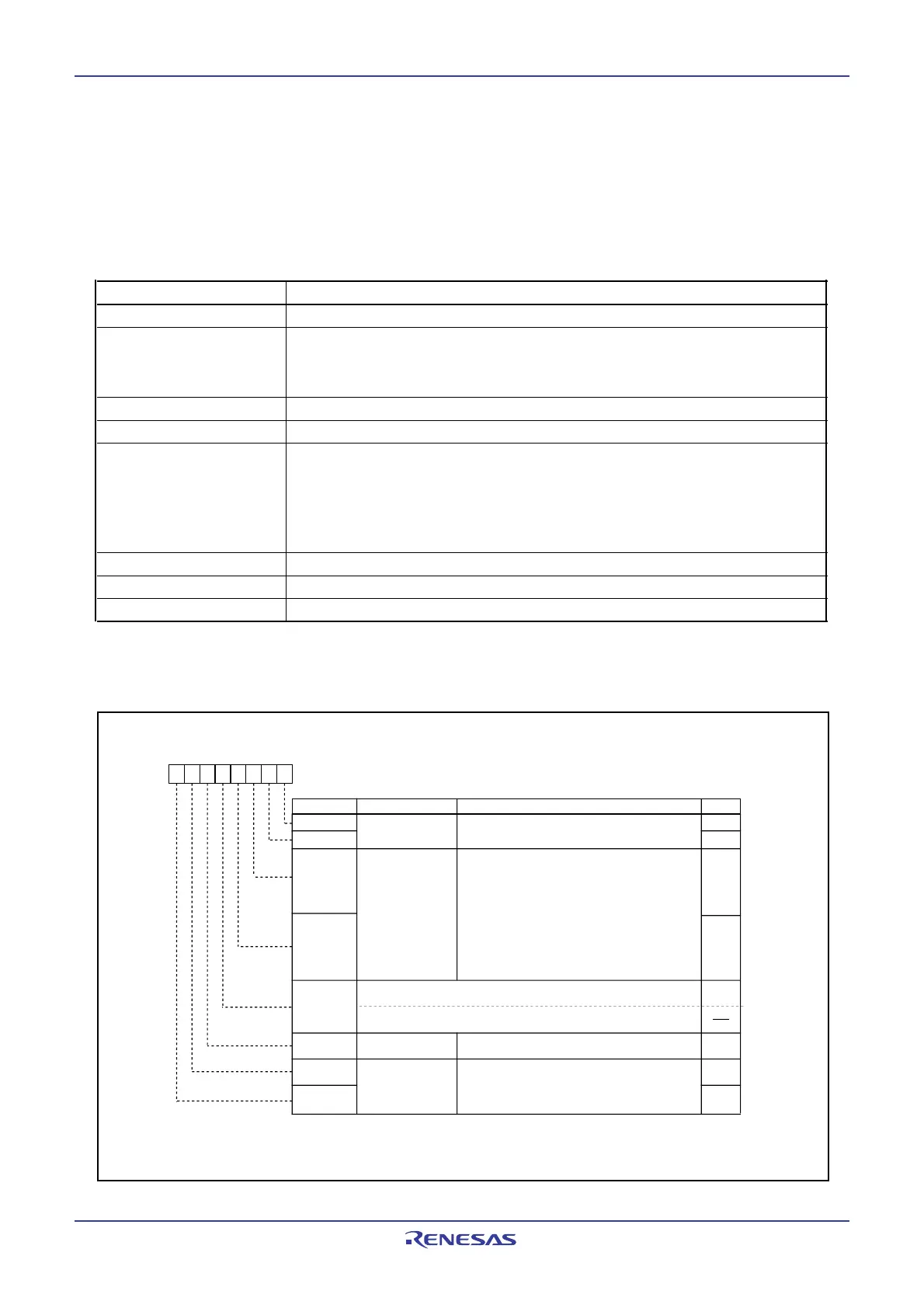
Figure 12.20
TBiMR Register in Pulse Period and Pulse Width Measurement Mode
Timer Bi Mode Register (i=0 to 2)
Symbol Address After Reset
TB0MR to TB2MR 039B
16
to 039D
16
00XX0000
2
Bit NameBit Symbol RW
b7 b6 b5 b4 b3 b2 b1 b0
Operation mode
select bit
1 0 : Pulse period / pulse width
measurement mode
b1 b0
TMOD1
TMOD0
MR0
Measurement mode
select bit
MR2
MR1
MR3
TCK1
TCK0
01
0 0: Pulse period measurement
(Measurement between a falling edge and the
next falling edge of measured pulse)
0 1: Pulse period measurement
(Measurement between a rising edge and the next
rising edge of measured pulse)
1 0: Pulse width measurement
(Measurement between a falling edge and the
next rising edge of measured pulse and between
a rising edge and the next falling edge)
1 1: Do not set.
Function
b3 b2
Count source
select bit
Timer Bi overflow
flag
(1)
0 : Timer did not overflow
1 : Timer has overflowed
0 0: f
1
or f
2
0 1: f
8
1 0: f
32
1 1: f
C32
b7 b6
NOTE:
1.This flag is undefined after reset. When the TBiS bit is set to 1 (start counting), the MR3 bit is cleared to 0 (no overflow) by
writing to the TBiMR register at the next count timing or later after the MR3 bit was set to 1 (overflowed). The MR3 bit cannot be
set to 1 by program. Bits TB0S to TB2S are assigned to the bit 5 to bit 7 in the TABSR register.
RO
TB0MR register
Set to 0 in pulse period and pulse width measurement mode
TB1MR, TB2MR registers
Nothing is assigned. If necessary, set to 0. When read, its content is undefined
RW
RW
RW
RW
RW
RW
RW
 Loading...


