9. Interrupts
puorG92/C61M
page 78
854fo7002,03.raM21.1.veR
2110-1010B90JER
9.3.1 I Flag
The I flag enables or disables the maskable interrupt. Setting the I flag to 1 (= enabled) enables the
maskable interrupt. Setting the I flag to 0 (= disabled) disables all maskable interrupts.
9.3.2 IR Bit
The IR bit is set to 1 (= interrupt requested) when an interrupt request is generated. Then, when the
interrupt request is accepted and the CPU branches to the corresponding interrupt vector, the IR bit is
cleared to 0 (= interrupt not requested).
The IR bit can be cleared to 0 in a program. Note that do not write 1 to this bit.
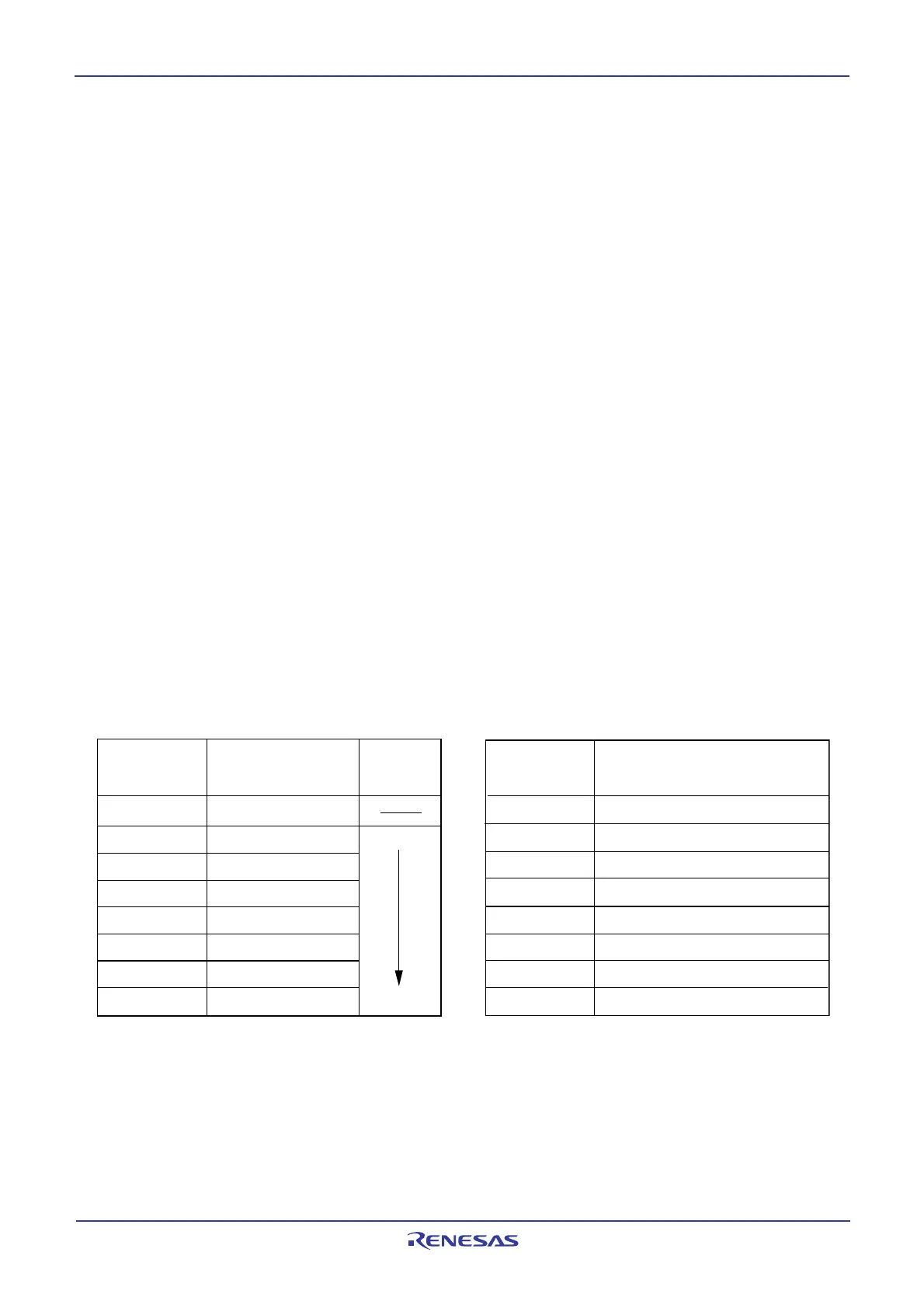
9.3.3 ILVL2 to ILVL0 Bits and IPL
Interrupt priority levels can be set using bits ILVL2 to ILVL0.
Table 9.3 shows the settings of interrupt priority levels and Table 9.4 shows the interrupt priority levels
enabled by the IPL.
The following are conditions under which an interrupt is accepted:
· I flag = 1
· IR bit = 1
· interrupt priority level > IPL
The I flag, IR bit, bits ILVL2 to ILVL0, and IPL are independent of each other. In no case do they affect
one another.
Table 9.4 Interrupt Priority Levels
Enabled by IPL
Table 9.3 Settings of Interrupt Priority
Levels
ILVL2 to ILVL0 bits
Interrupt priority
level
Priority
order
000
2
001
2
010
2
011
2
100
2
101
2
110
2
111
2
Level 0 (interrupt disabled)
Level 1
Level 2
Level 3
Level 4
Level 5
Level 6
Level 7
Low
High
Enabled interrupt priority levels
Interrupt levels 1 and above are enabled
Interrupt levels 2 and above are enabled
Interrupt levels 3 and above are enabled
Interrupt levels 4 and above are enabled
Interrupt levels 5 and above are enabled
Interrupt levels 6 and above are enabled
Interrupt levels 7 and above are enabled
All maskable interrupts are disabled
IPL
000
2
001
2
010
2
011
2
100
2
101
2
110
2
111
2
 Loading...


