7. Clock Generation Circuit
page 55
854fo7002,03.raM21.1.veR
2110-1010B90JER
puorG92/C61M
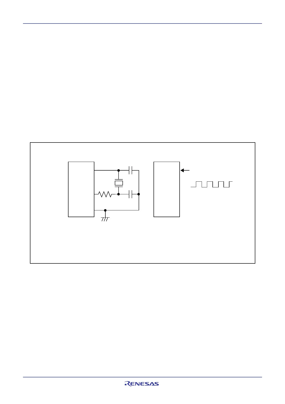
Figure 7.9 Examples of Sub Clock Connection Circuit
7.2 Sub Clock
The sub clock is generated by the sub clock oscillation circuit. This clock is used as the clock source for the
CPU clock, as well as the timer A and timer B count sources.
The sub clock oscillator circuit is configured by connecting a crystal resonator between the XCIN and XCOUT
pins. The sub clock oscillator circuit contains a feedback resistor, which is disconnected from the oscillator
circuit during stop mode in order to reduce the amount of power consumed in the chip. The sub clock
oscillator circuit may also be configured by feeding an externally generated clock to the XCIN pin. Figure
7.9 shows the examples of sub clock connection circuit.
After reset, the sub clock is turned off. At this time, the feedback resistor is disconnected from the oscillator
circuit.
To use the sub clock for the CPU clock, set the CM07 bit in the CM0 register to 1 (sub clock) after the sub
clock becomes oscillating stably.
During stop mode, all clocks including the sub clock are turned off. Refer to “power control”.
External Clock
X
C
IN
X
C
OUT
Open
V
CC
VSS
NOTE:
1. Place a damping resistor if required. Resistance values vary depending on the oscillator setting.
Use values recommended by each oscillator manufacturer.
Place a feedback resistor between X
CIN and XCOUT if the oscillator manufacturer recommends
placing the resistor externally.
Oscillator
R
Cd
(1)
CCIN
CCOUT
XCIN
XCOUT
MCU
(Built-in Feedback Resistor)
MCU
(Built-in Feedback Resistor)
V
SS
 Loading...


