5. Resets
puorG92/C61M
page 38
854fo7002,03.raM21.1.veR
2110-1010B90JER
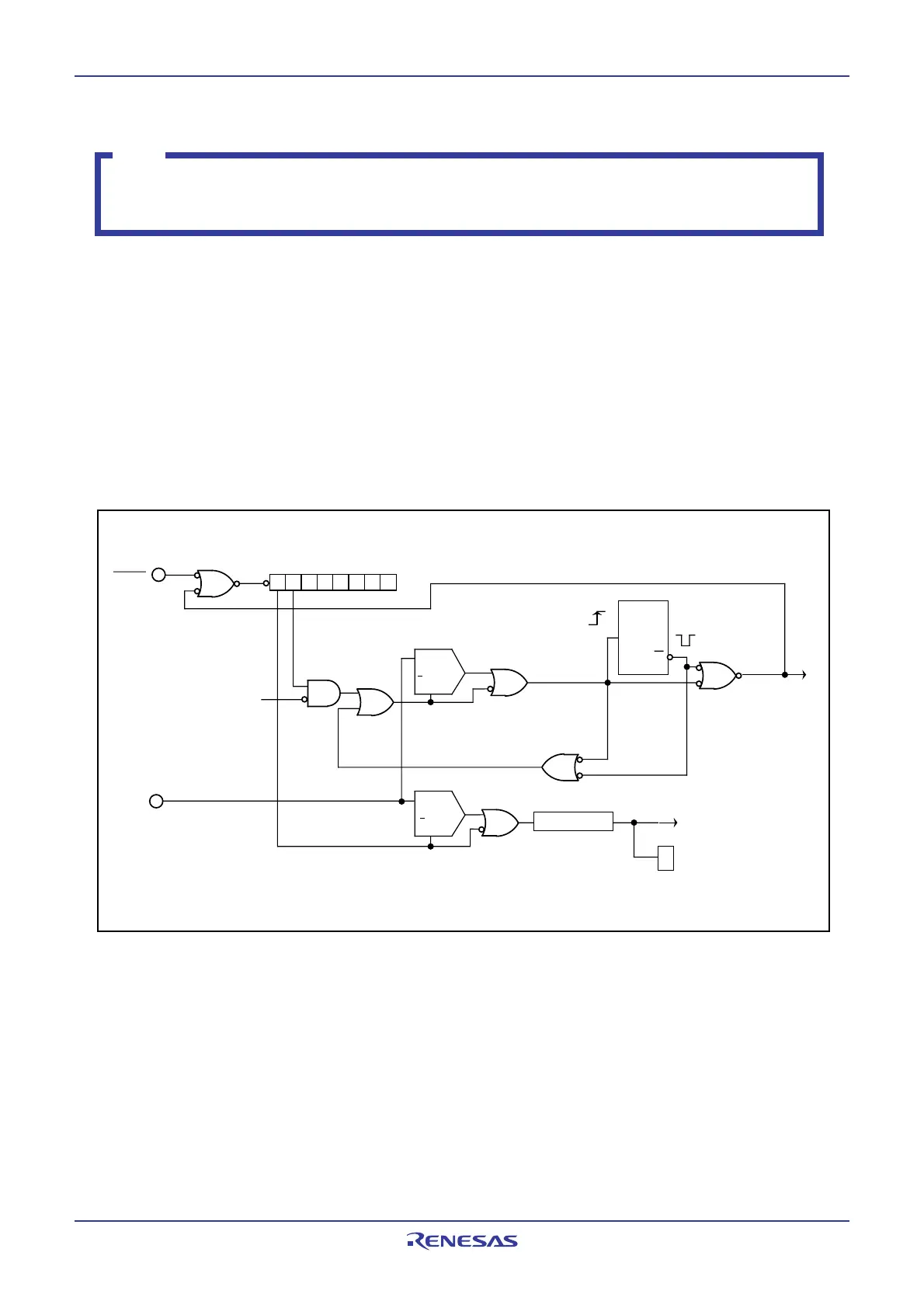
5.5 Voltage Detection Circuit
Note
VCC = 5 V is assumed in 5.5 Voltage Detection Circuit.
Voltage detection circuit in the M16C/29 Group, T-ver. and V-ver. cannot be used.
The voltage detection circuit has the reset level detection circuit and the low voltage detection circuit. The
reset level detection circuit monitors the voltage applied to the VCC pin. The MCU is reset if the reset level
detection circuit detects VCC is Vdet3 or below. Use bits VC27 and VC26 in the VCR2 register to determine
whether the individual circuit is enabled.
Use the reset level detection circuit for brown-out detection reset.
The low voltage detection circuit also monitors the voltage applied to the VCC pin. The low voltage detec-
tion circuit use the VC13 bit in the VCR1 register to detect VCC is above or below Vdet4. The low voltage
detection interrupt can be used in the voltage detection circuit.
Figure 5.4 Voltage Detection Circuit Block
b7 b6
VCR2 Register
RESET
CM10 Bit=1
(Stop Mode)
+
>Vdet3
+
>Vdet4
E
Noise Rejection
Low Voltage
Detect Signal
b3
VCR1 Register
VC13 Bit
>T
Q
1 shot
Internal Reset Signal
(“L” active)
E
VCC
td(S-R)
Brown-out Detect Reset
(Hardware Reset 2
Release Wait Time)
Reset level
detection circuit
Low voltage
detection circuit
 Loading...


