5. Resets
puorG92/C61M
page 37
854fo7002,03.raM21.1.veR
2110-1010B90JER
____________
Table 5.1 Pin Status When RESET Pin Level is “L”
Status
Pin name
P0 to P3,
P6 to P10
Input port (high impedance)
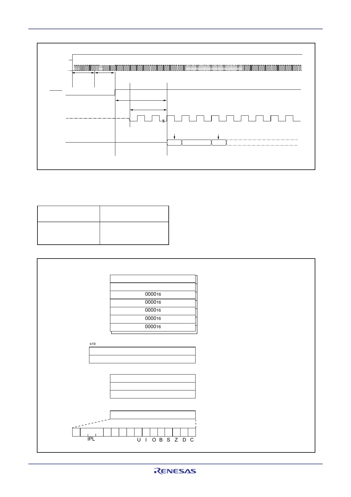
Figure 5.3 CPU Register Status After Reset
b15
b0
Data register(R0)
Address register(A0)
Frame base register(FB)
Program counter(PC)
Interrupt table register(INTB)
User stack pointer(USP)
Interrupt stack pointer(ISP)
Static base register(SB)
Flag register(FLG)
0000
16
0000
16
0000
16
CDZSBOIU
IPL
0000
16
0000
16
0000
16
0000
16
0000
16
b19
b0
Content of addresses FFFFE
16
to FFFFC
16
b15
b0
b15
b0
b15
b0
b7 b8
00000
16
Data register(R1)
Data register(R2)
Data register(R3)
Address register(A1)
0000
16
0000
16
0000
16
Figure 5.2 Reset Sequence
td(P-R) More than
td(ROC)
CPU clock
Address
ROC
RESET
Content of reset vector
CPU clock: 28 cycles
FFFFE
16
FFFFC
16
V
CC
Max. 2 ms
 Loading...


