9. Interrupts
puorG92/C61M
page 84
854fo7002,03.raM21.1.veR
2110-1010B90JER
Timer B2
Timer B0
Timer A3
Timer A1
Timer B1
Timer A4
Timer A2
UART1 reception
UART0 reception
UART2 reception, ACK2
A/D conversion, Key input interrupt
DMA1
UART 2 bus collision
Timer A0
UART1 transmission
UART0 transmission
UART2 transmission, NACK2
CAN 0 error
DMA0
IPL
I flag
INT1
INT2
INT0
Watchdog time
r
DB
C
NM
I
Interrupt
request
accepted
Level 0 (initial value)
Priority level of each interrupt
Highest
Lowest
Priority of peripheral function interrupts
(if priority levels are same)
ICOC interrupt 1, I
2
C bus interface
INT3
ICOC base timer, S
CL
/S
DA
ICOC interrupt 0
SI/O4, INT5
SI/O3, INT4
Address match
Interrupt request level resolution output to clock
generating circuit (See Figure.7.1
)
Oscillation stop and
re-oscillation detection
Low voltage detection
CAN 0 wakeup
CAN 0 reception
CAN 0 transmission
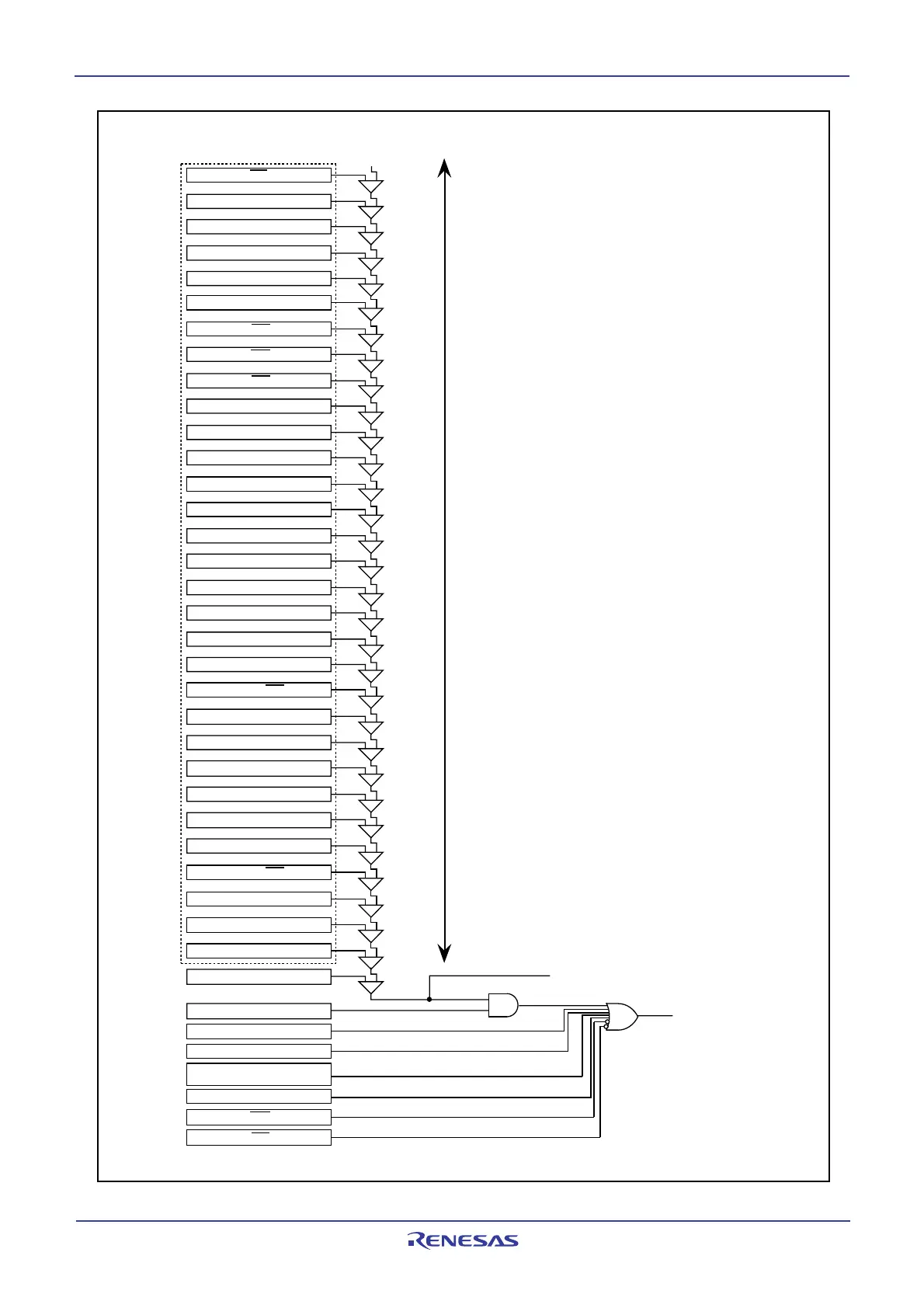
Figure 9.10 Interrupts Priority Select Circuit
 Loading...


