12. Timer (Three-phase Motor Control Timer Function)
puorG92/C61M
page 137
854fo7002,03.raM21.1.veR
2110-1010B90JER
12.3.1.2 Position-data-retain Function Control Register
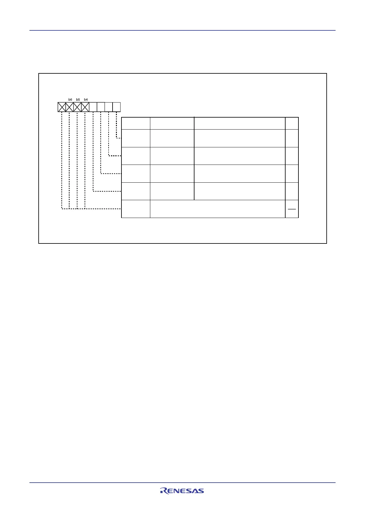
Figure 12.36 shows the structure of the position-data-retain function contol register.
Figure 12.36 PDRF Register
12.3.1.2.1 W-phase Position Data Retain Bit (PDRW)
This bit is used to retain the input level at pin IDW.
12.3.1.2.2 V-phase Position Data Retain Bit (PDRV)
This bit is used to retain the input level at pin IDV.
12.3.1.2.3 U-phase Position Data Retain Bit (PDRU)
This bit is used to retain the input level at pin IDU.
12.3.1.2.4 Retain-trigger Polarity Select Bit (PDRT)
This bit is used to select the trigger polarity to retain the position data.
When this bit is set to 0, the rising edge of each positive phase selected.
When this bit is set to 1, the falling edge of each pocitive phase selected.
Position-Data-Retain Function
ontrol Re
ister
(1)
Symbol Address After Reset
PDRF 034E
16
XXXX 0000
2
RO
RO
RO
RWBit Name FunctionBit Symbol
PDRW
PDRV
PDRU
W-phase position
data retain bit
Input level at pin IDU is read out.
0: "L" level
1: "H" level
NOTE:
1.This register is valid only in the three-phase mode.
Retain-trigger
polarity select bit
(b7-b4)
RW
PDRT
V-phase position
data retain bit
Nothing is assigned. If necessary, set to 0. When read,
the contents are undefined
U-phase position
data retain bit
Input level at pin IDV is read out.
0: "L" level
1: "H" level
Input level at pin IDW is read out.
0: "L" level
1: "H" level
0: Rising edge of positive phase
1: Falling edge of positive phase
7
2b1b0
 Loading...


