16. MULTI-MASTER I
2
C bus INTERFACE
puorG92/C61M
page 266
854fo7002,03.raM21.1.veR
2110-1010B90JER
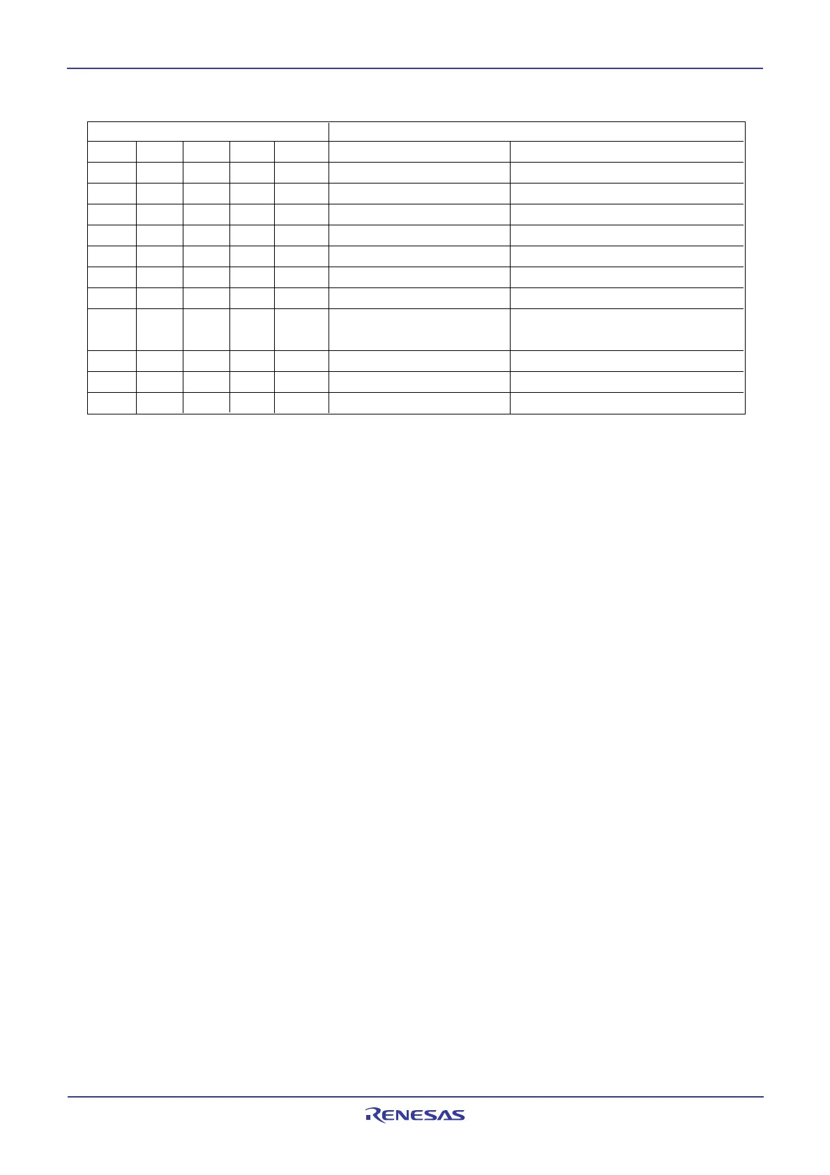
Setting value of CCR4 to CCR0 SCL frequency (at VIIC=4MHz, unit : kHz) (1)
CCR4 CCR3 CCR2 CCR1 CCR0 Standard clock mode High-speed clock mode
0 0 0 0 0 Setting disabled Setting disabled
0 0 0 0 1 Setting disabled Setting disabled
0 0 0 1 0 Setting disabled Setting disabled
0 0 0 1 1 -
(2)
333
0 0 1 0 0 -
(2)
250
0 0 1 0 1 100 400
(3)
0 0 1 1 0 83.3 166
500 / CCR value
(3)
1000 / CCR value
(3)
1 1 1 0 1 17.2 34.5
1 1 1 1 0 16.6 33.3
1 1 1 1 1 16.1 32.3
NOTES:
1. The duty of the SCL clock output is 50 %. The duty becomes 35 to 45 % only when high-speed
clock mode is selected and the CCR value = 5 (400 kHz, at VIIC = 4 MHz). “H” duration of the
clock fluctuates from –4 to +2 I
2
C system clock cycles in standard clock mode, and fluctuates from
–2 to +2 I
2
C system clock cycles in high-speed clock mode. In the case of negative fluctuation,
the frequency does not increase because the “L” is extended instead of “H” reduction. These are
the values when the SCL clock synchronization by the synchronous function is not performed.
The CCR value is the decimal notation value of the CCR4 to CCR0 bits.
2. Each value of the SCL frequency exceeds the limit at VIIC = 4 MHz or more. When using these
setting values, use VIIC = 4 MHz or less. Refer to Figure 16.6.
3. The data formula of SCL frequency is described below:
VIIC/(8 x CCR value) Standard clock mode
VIIC/(4 x CCR value) High-speed clock mode (CCR value ≠ 5)
VIIC/(2 x CCR value) High-speed clock mode (CCR value = 5)
Do not set 0 to 2 as the CCR value regardless of the VIIC frequency. Set 100 kHz (max.) in
standard clock mode and 400 kHz (max.) in high-speed clock mode to the SCL frequency by
setting the CCR4 to CCR0 bits.
Table 16.3 Setting values of S20 register and SCL frequency
→
→
→
→
→
 Loading...


