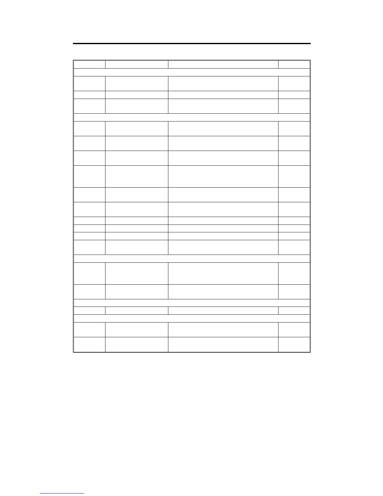
3. ELECTRICAL COMPONENT DESCRIPTION
Symbol Name Function Index No.
Motors
M1 Feed-in
Drives the feed-in system (pick-up, feed
and pull-out rollers, separation belt)
5
M2 Belt Drive Drives the transport belt 6
M3 Feed-out
Drives the feed-out and the inverter
system
10
Sensors
S1 Original Set
Detects whether originals have been
placed on the original table
1
S2 Feed-in Cover Open
Informs whether the feed-in cover is open
or not
2
S3 Feed-out Cover Open
Informs whether the feed-out cover is
open or not
9
S4 Feed-out
Checks for original misfeeds and
determines original stop timing when in
auto-reverse mode
11
S5 APS Start
Informs the CPU that it is time to detect
the original size (in platen mode)
12
S6 DF Position
Informs the CPU whether the DF is in the
up or down position
13
S7 Original Width-1 Detects the width of the original 14
S8 Original Width-2 Detects the width of the original 15
S9 Original Width-3 Detects the width of the original 16
S10 Registration
Determines original stop timing and
measures the length of the original
17
Solenoids
SOL1 Stopper
Lifts the original stopper and lowers the
feed-in lever to feed the set of originals to
the feed roller
3
SOL2 Inverter
Energizes to invert the original when
copying two-sided originals
8
PCB
PCB1 DF Main Board Controls all DF functions 7
Indicators (Lamps)
L1 Ready
Informs the operator that the DF is in the
down position.
4
L2 Auto
Informs the operator that the auto feed
mode is available.
4
A156/A160/A162 3-4 STM

 Loading...