1.3 IMAGE DENSITY CONTROL
1.3.1 Overview
The machine controls the toner supply mechanism using the toner density
sensor (TD sensor) and the image density sensor (ID sensor).
Readings from the TD sensor are used to keep the toner concentration in the
developer at a constant level. However, the image on the OPC drum varies
due to the variation in toner chargeability, which is influenced by the
environment, even if the toner concentration is constant. Because of this,
readings from the ID sensor are used to change the toner concentration to
keep the image density on the OPC drum constant.
1.3.2 V
SP
and V
SG
Detection
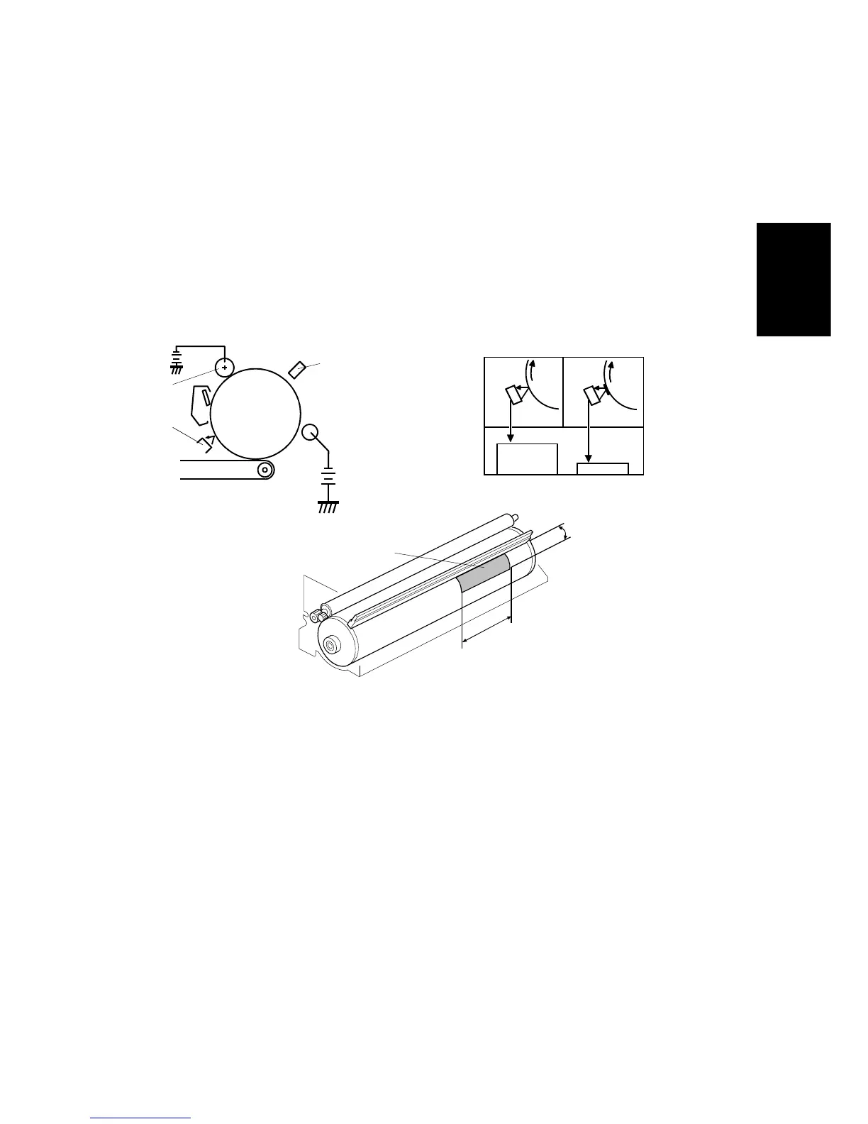
The ID sensor [A] (below the drum cleaning section) checks the following
voltages.
• V
SG
: the ID sensor output when checking the erased drum surface.
•
V
SP
: the ID sensor output when checking the Vsp pattern image.
In this way, the reflectivity of both the erased drum surface and the pattern
on the drum are checked. This compensates for any variations in light
intensity from the LED component of the sensor or the reflectivity of the drum.
The V
SP
pattern [B] is made on the OPC drum by the drum charge roller [C]
and the erase lamp [D].
65 mm
35 mm
[B]
[C]
[A]
[D]
Dev.
bias
Drum
LED
ON
LED
ON
V
SG
V
SP
Detailed
Descriptions
STM 2-11 A156/A160/A162

 Loading...