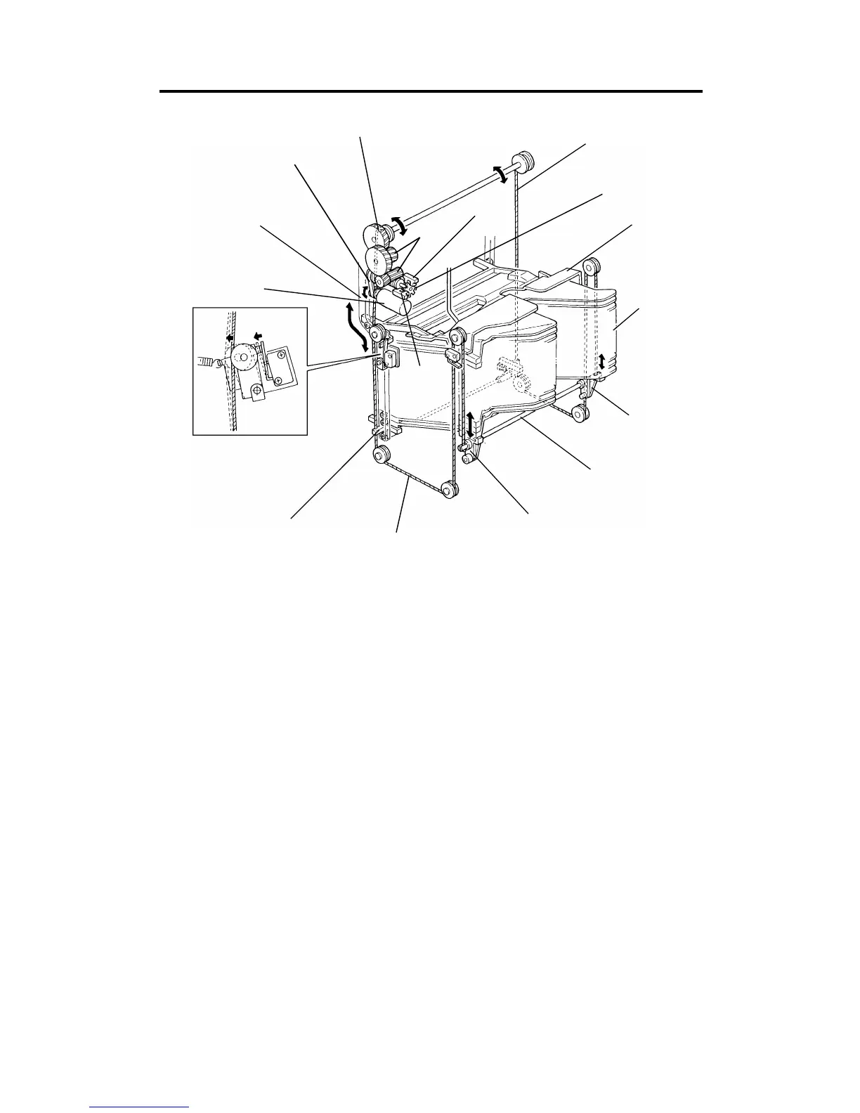
6. BIN DRIVE AND CONTROL
All the 20 bins [A] and the support bin [B] are piled up on the bin support
blocks [C]. The front and rear bin support blocks are connected by the bin lift
shafts [D], the ends of which are fixed to the bin lift wires [E] as shown. The
bin lift motor [F] (dc motor) drives the bin lift wires through the bin lift drive
belt [G], bin lift gears [H], and the bin lift gear/pulley [I]. Then the bins are
driven up and down along the front and rear bin cam tracks [J].
The S/S CPU controls the amount of bin lift motor rotation by monitoring the
pulses from the timing disc [K] through the bin lift timing sensors 1 and 2 [L
and M]. Bin lift timing sensor 1 (blue connector) is used for counting the
timing pulses. Bin lift timing sensor 2 (white connector) is used to determine
the motor stop timing so that the edge of the timing disc slots is not
positioned at timing sensor 1.
[J]
[G]
[F]
[I]
[C]
[L]
[E]
[H]
[M]
[E]
[K]
[B]
[A]
[C]
[D]
[C]
A156/A160/A162 6-14 STM