1.2.3 ADS Correction
If the user selects Auto Image Density (ADS) mode, the output of the ADS
sensor is used to correct the development bias; the exposure lamp voltage is
kept at the setting for ID level 4 and is not adjusted.
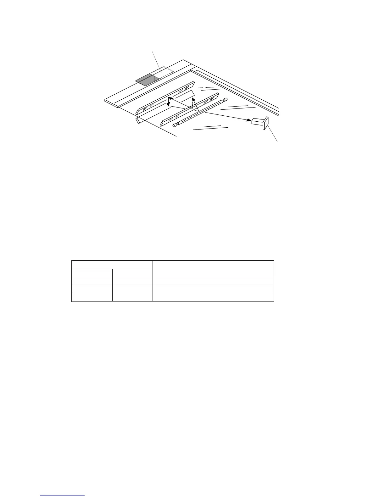
In ADS mode, the ADS sensor [A] detects the original background density.
To prevent dirty background from appearing on copies, the CPU corrects the
development bias voltage for the original. To do this, it compares the ADS
sensor output from the original [V
ADS
(original)] with a stored reference value
[V
ADS
(pattern)] that was taken earlier from the ADS sensor pattern. The
correction is shown in table 5, and is applied every copy.
Table 5. ADS data correction
ADS Density SP5-106
Development Bias Correction Voltage
Setting
Copy Density
0 Darker 816 x (AR – 0.79)
1 Normal 816 x (AR – 0.85)
2 Lighter 816 x (AR – 0.95)
Where AR (ADS Ratio) = V
ADS
(original)/V
ADS
(pattern)
Note that there are three possible corrections. The default setting is 1
(normal). However, for example, if the user requires copies to be darker
when using ADS mode, a technician can set SP5-106 to 0.
V
ADS
(pattern) is checked every 1,000 copies. (See process control checks
at every 1,000 copies on p2-29.) It is kept at 2.7
±
0.1 volts by a gain
adjustment.
See the "Optics - Automatic Image Density Control System (ADS)" section
for more details on how the ADS sensor measures the background and on
how [V
ADS
(pattern)] is corrected every 1,000 copies.
ADS pattern
[A]
Fig. 3 ADS pattern
A156/A160/A162 2-10 STM

 Loading...