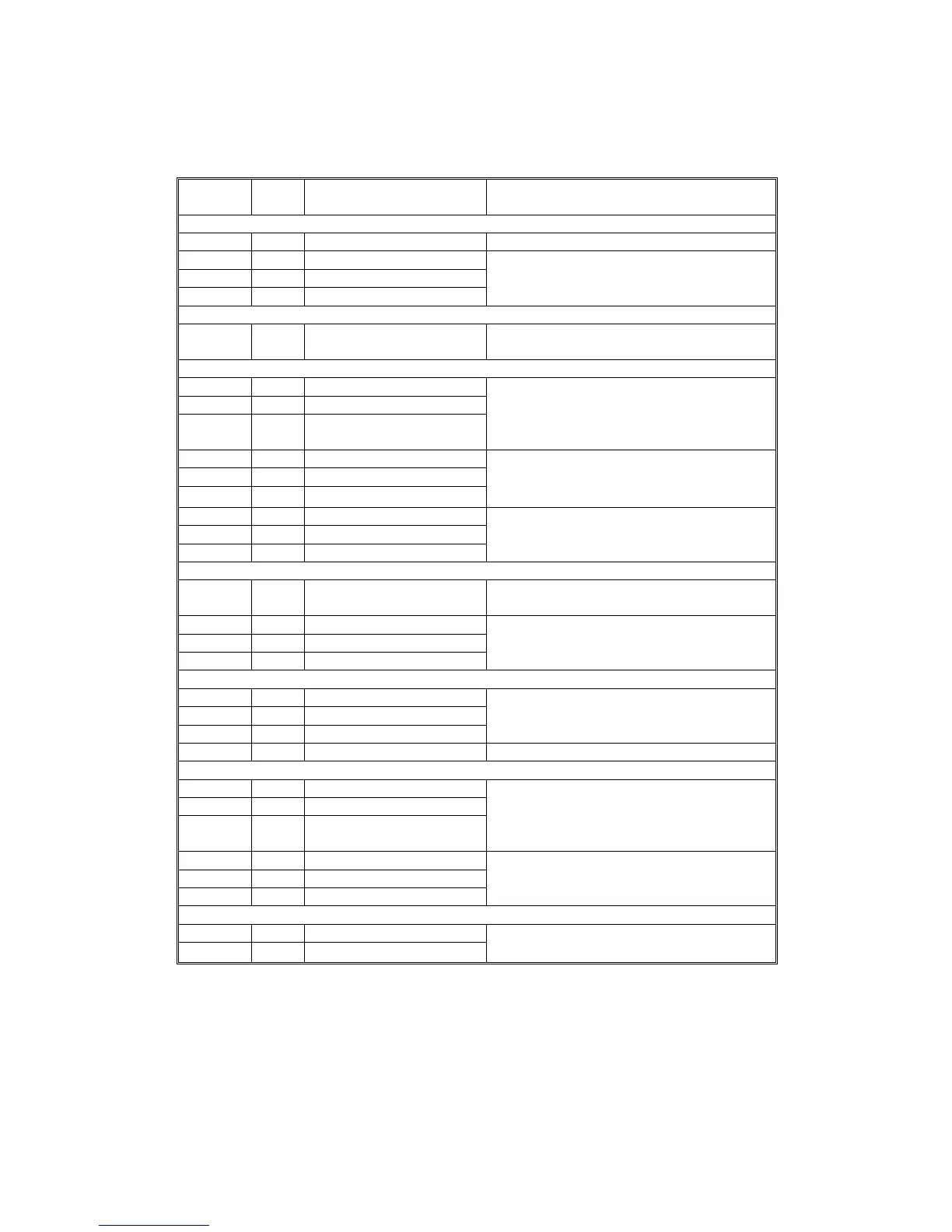
2.3 ELECTRICAL COMPONENT DESCRIPTION
Refer to the electrical component layout on the reverse side of the Point to
Point Diagram (on waterproof paper).
Symbol
Index
No.
Description Note
Motors
M1 5 Main Drives all the components of the paper tray
M2 2 Tray lift 1
Raises the bottom plate in the paper tray
M3 30 Tray lift 2
M4 29 Tray lift 3 (A549 only)
Circuit board
PCB1 1 Interface board
Controls the paper tray in response to
signals from the copier
Sensors
S1 7 Tray upper limit 1
Detects the top of the stack to stop the tray
lift motor
S2 18 Tray upper limit 2
S3 19
Tray upper limit 3 (A549
only)
S4 25 Relay 1 Detects the leading edge of the paper as it
leaves the tray to control pick-up solenoid
and jam detection timing
S5 23 Relay 2
S6 20 Relay 3 (A549 Only)
S7 28 Paper end 1
Detects when the paper tray is empty
S8 24 Paper end 2
S9 21 Paper end 3 (A549 only)
Switches
SW1 22 Tray cover
Detects whether the tray unit cover is open
and cuts the 24 Vdc power if it is
SW2 3 Tray set 1
Detects whether the paper tray is in place
SW3 4 Tray set 2
SW4 6 Tray set 3 (A549 only)
Magnetic clutches
CL1 9 Paper feed 1
Starts feeding paper from the tray
CL2 12 Paper feed 2
CL3 15 Paper feed 3 (A549 only)
CL4 11 Relay Drives the rollers in the paper trays
Solenoids
SOL1 8 Paper pick-up 1
Lifts/drops the pick-up roller
SOL2 13 Paper pick-up 2
SOL3 16
Paper pick-up 3 (A549
only)
SOL4 10 Separation 1
Lifts/drops the separation roller
SOL5 14 Separation 2
SOL6 17 Separation 3 (A549 Only)
Heaters
H1 26 Tray (Option) Turns on when the main switch is off to
keep the paper in the trays dry
H2 27 Tray (Option)
Rev. 7/95
A156/A160/A162 4-4 STM

 Loading...