Publication 2711P-UM001D-EN-P - September 2005
5-4 Install and Replace Components
Install or Replace
the Logic Module
This section shows how to install and replace the logic module. If the
display module and logic module are ordered as separate
components, attach the logic module to the display module before
panel installation.
The logic module is available with or without RAM and internal
compact flash installed. If ordered as separate components, you must
install the memory before attaching the logic module to the display
module.
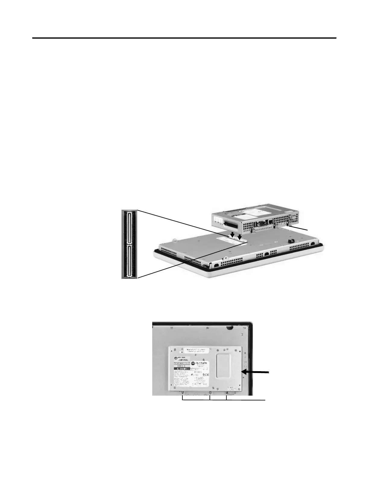
To install a logic module:
1. Disconnect power from the terminal.
2. If the terminal is removed from panel, set the terminal, display
side down, on a clean, flat, stable surface to prevent scratches.
3. Position the logic module over the back of the display module
until the two connectors on the bottom of the logic module align
with the connectors on the display module.
4. Push down on the logic module until firmly seated.
5. Tighten the six captive screws that secure the logic module to
the display module to a torque of 0.68 Nm
(6 to 8 in-lb).
700 - 1500 Terminals Only
Captive
Screw
Logic Module
Captive screws
on top and bottom

 Loading...