Publication 2711P-UM001D-EN-P - September 2005
Installation 2-5
Mount the terminal vertically to minimize solar loading on the display.
Do not mount the terminal in a sloped enclosure if it will be exposed
to direct sunlight.
Required Tools
• Panel cutout tools
• Small, slotted screw driver for securing power and RS-232
connections
• Torque wrench (in-lb) for tightening the mounting clips on the
PanelView Plus 700-1500 terminals
Clearances
Allow adequate clearance around the terminal, inside the enclosure,
for adequate ventilation. Consider heat produced by other devices in
the enclosure. The ambient temperature around the terminals must be
between 0 to 55 °C (32 to 131 ºF).
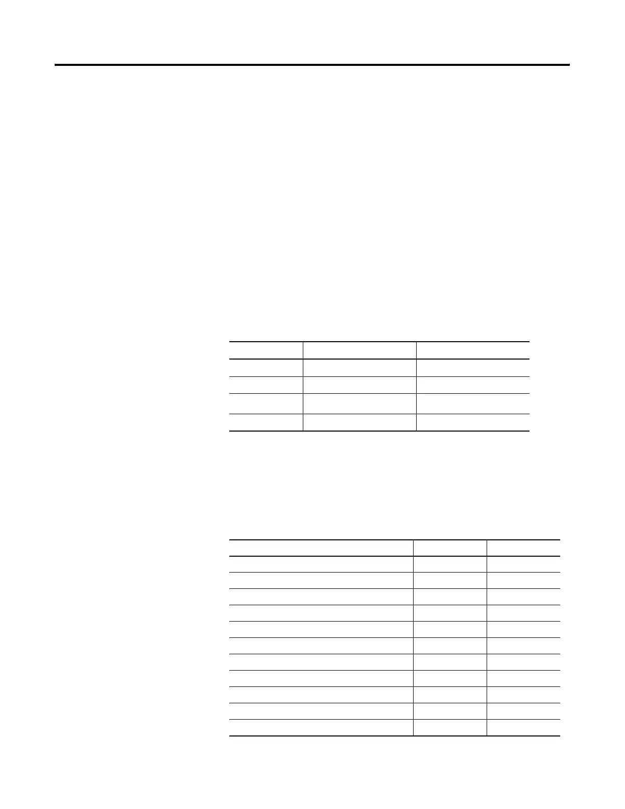
Panel Cutout Dimensions
The table lists the panel cutout dimensions for each terminal. Use the
full size template shipped with your terminal to mark the cutout
dimensions.
Clearance Area 400 and 600 Terminals 700 - 1500 Terminals
Top 51 mm (2 in) 51 mm (2 in)
Bottom 102 mm (4 in) 51 mm (2 in)
Side
(1)
(1)
Minimum side clearance for insertion of memory card and cable wiring is 102 mm (4 in).
25 mm (1 in) 25 mm (1 in)
Back none 25 mm (1 in)
PanelView Plus Terminals Height mm (in) Width mm (in)
400 Keypad 123 (4.86) 156 (6.15)
600 Keypad or Keypad & Touch 142 (5.61) 241 (9.50)
600 Touch 123 (4.86) 156 (6.15)
PanelView Plus 700 Keypad or Keypad & Touch 167 (6.57) 264 (10.39)
PanelView Plus 700 Touch 154 (6.08) 220 (8.67)
PanelView Plus 1000 Keypad or Keypad & Touch 224 (8.8) 375 (14.75)
PanelView Plus 1000 Touch 224 (8.8) 305 (12.00)
PanelView Plus 1250 Keypad or Keypad & Touch 257 (10.11) 390 (15.35)
PanelView Plus 1250 Touch / 1250 High-Bright Touch 257 (10.11) 338 (13.29)
PanelView Plus 1500 Keypad or Keypad & Touch 305 (12.00) 419 (16.50)
PanelView Plus 1500 Touch 305 (12.00) 391 (15.40)

 Loading...