Publication 2711P-UM001D-EN-P - September 2005
Install and Replace Components 5-19
10. Reattach the LCD display connector to the circuit board.
11. Reattach the backlight connector to the circuit board.
12. Secure the LCD display by attaching the four screws and tighten
to the specified torque.
13. Replace the display module bezel.
Install the Remote AC
Power Supply
Connecting to AC power requires a separate power supply, cat. no.
2711P-RSACDIN that mounts to a DIN Rail. This power supply
converts AC power to DC power and has these electrical input ratings:
• 85 to 264 V AC (47 to 63 Hz)
For details on installation, refer to the installation instructions shipped
with the power supply.
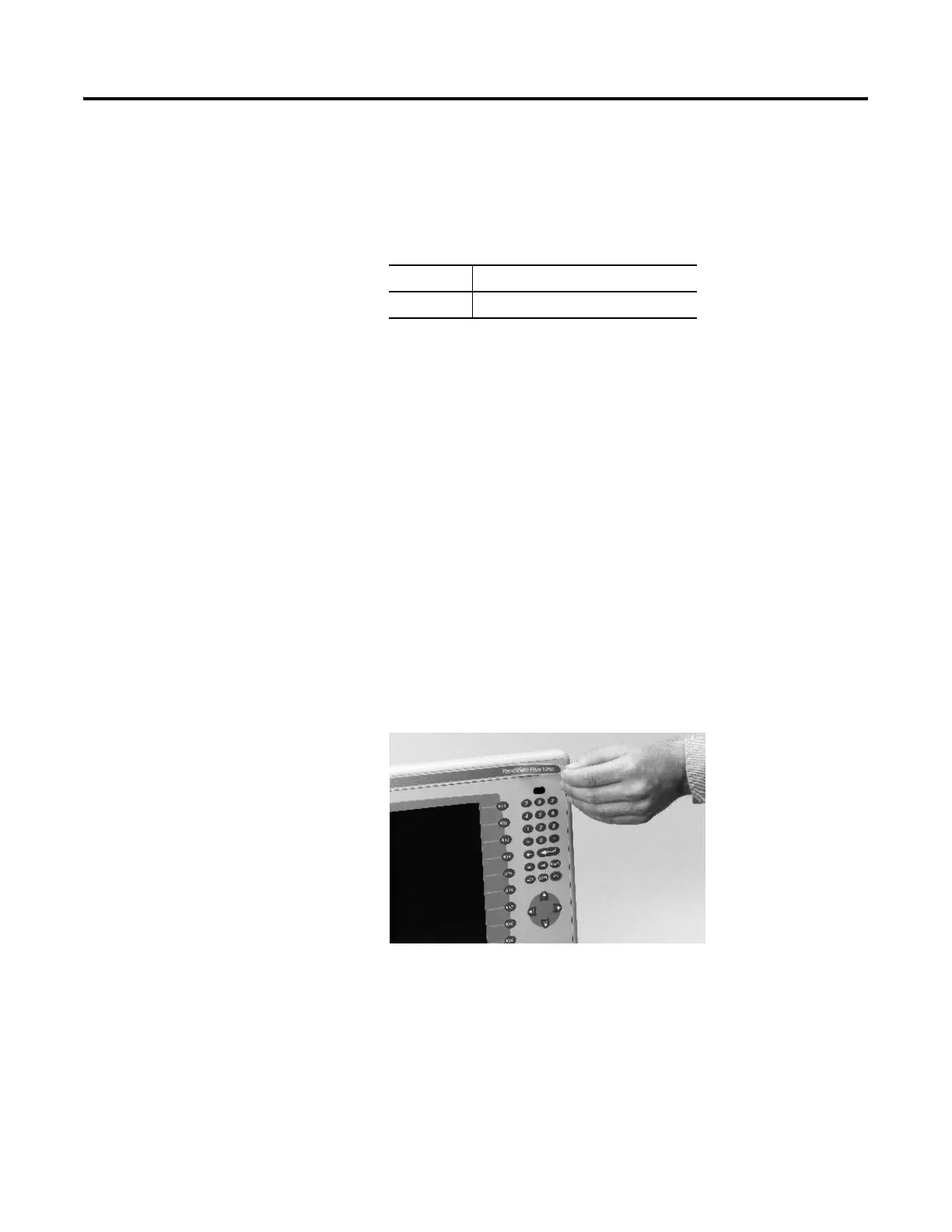
Remove the Product ID
Label
If you ordered a terminal with a label, you can remove it and attach
your own label.
1. Remove the Allen-Bradley label using your fingers or a tweezers.
2. Clean area with damp cloth and isopropyl alcohol.
3. Remove adhesive backing of OEM label and affix over area
where Allen-Bradley label was located.
Screw Size Torque
#4 0.68 Nm (6 to 8 in-lb)
00 - 1500 Terminals Only

 Loading...