EasyManua.ls Logo

Rockwell Automation Allen-Bradley PanelView Plus Series User Manual

Rockwell Automation Allen-Bradley PanelView Plus Series
193 pages
To Next Page IconTo Next Page
To Previous Page IconTo Previous Page
Page #145 background image
Publication 2711P-UM001D-EN-P - September 2005
Terminal Connections 6-23
Minimum Requirements
DeviceNet Connections
2711P-RN10C DeviceNet Module for 400 and 600 Terminals
2711P-RN10H DeviceNet Module for 700-1500 Terminals
Software/Firmware PanelView Plus 700-1500 PanelView Plus 400 and 600
RSView Studio v4.0 or later v4.0 or later
RSView Machine Edition Runtime v4.0 or later v4.0 or later
DeviceNet Module 2711P-RN10H 2711P-RN10C
I/O Status Indicator
MOD Status Indicator
NET Status
Indicator
Red
White
Shield
Blue
Black
MOD Status Indicator
I/O Status Indicator
NET Status
Indicator
Red
White
Shield
Blue
Black

Table of Contents

Question and Answer IconNeed help?

Do you have a question about the Rockwell Automation Allen-Bradley PanelView Plus Series and is the answer not in the manual?

Rockwell Automation Allen-Bradley PanelView Plus Series Specifications

General IconGeneral
MountingPanel mount
Display Size7", 10", 15"
Display TypeTFT LCD
Resolution1024 x 768
Communication PortsEthernet, USB, RS-232
Power Supply24V DC
Operating Temperature0°C to 50°C (32°F to 122°F)
Operating SystemWindows CE
Enclosure RatingNEMA 4X

Summary

Chapter 1 Overview

Chapter 2 Installation

Mount the 400 or 600 Terminal in a Panel

Step-by-step instructions for securely mounting PanelView Plus 400 and 600 terminals into a panel.

Mount the 700-1500 Terminal in a Panel

Step-by-step instructions for securely mounting PanelView Plus 700-1500 terminals into a panel.

Chapter 3 Connect Power

DC Power Connections

Details electrical input ratings, wire sizes, and functional earth connection for DC power.

AC Power Connections

Details electrical input ratings and protective earth connection for AC power.

Chapter 4 Configuration Mode

Load an ME Application

Provides steps for loading an RSView ME .MER application file onto the terminal.

IP Address

Identifies the IP address of the network adapter or allows manual assignment if DHCP is not used.

Touch Screen Calibration

Calibrates the touch screen by guiding the user through touching specific targets on the screen.

Chapter 5 Install and Replace Components

Compatibility of Terminal Components

Verifies compatibility of internal compact flash with logic module, and RSView ME version.

Install RAM or Internal Compact Flash

Step-by-step instructions for installing or replacing RAM and internal compact flash modules.

Install or Replace the Logic Module

Instructions for installing or replacing the logic module on the terminal.

Install or Replace a Communication Module

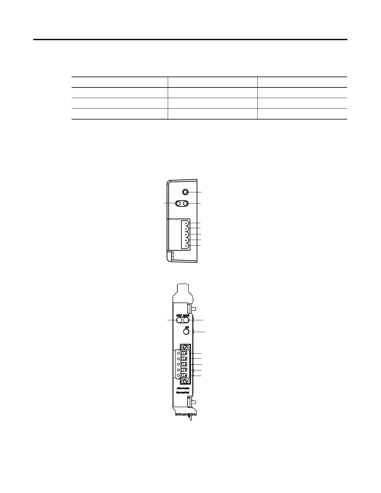
Steps to install or replace communication modules on the logic module.

Chapter 6 Terminal Connections

Logic Controller Cable Charts

Summarizes terminal connections to controllers and network interface modules with cable details.

Serial Connections

Details the RS-232 port capabilities, pinouts, and computer connection methods.

Ethernet Connections

Covers Ethernet port support, connector pinouts, and cable specifications.

Chapter 7 Transfer files and Upgrade Firmware

Chapter 8 Troubleshooting

Related product manuals