Do you have a question about the Rockwell Automation PanelView Plus 1000 and is the answer not in the manual?
| Display Size | 10.4 inches |
|---|---|
| Touchscreen Type | Analog resistive |
| Memory | 128 MB RAM |
| Operating System | Windows CE |
| Power Supply | 24 V DC |
| Storage | CompactFlash |
| Display Type | Color TFT LCD |
| Communication Ports | Ethernet, RS-232, USB |
| Enclosure | NEMA 4X |
| Operating Temperature | 0°C to 50°C |
| Enclosure Rating | NEMA 4X/IP65 |
| Resolution | 640 x 480 pixels |
Describes features of PanelView Plus 400 and 600 terminals, including base units and communication modules.
Provides an overview of PanelView Plus 700, 1000, 1250, 1250H, and 1500 terminals.
Shows catalog number configuration for PanelView Plus and PanelView Plus CE terminals.
Details suitability of equipment for various hazardous location classifications.
Discusses environmental considerations and enclosure requirements for terminal installation.
Step-by-step instructions for mounting PanelView Plus 400 and 600 terminals in a panel.
Step-by-step instructions for mounting PanelView Plus 700 to 1500 terminals in a panel.
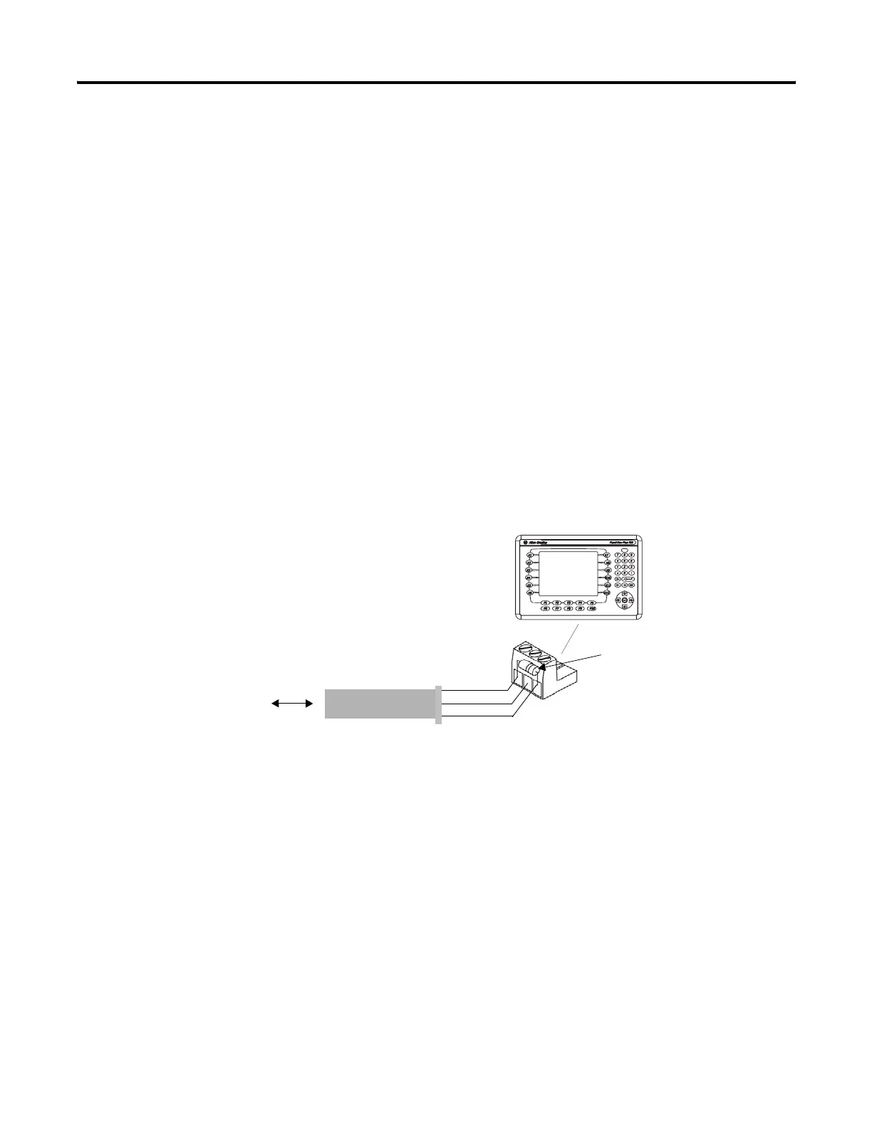
Details power ratings and wire specifications for DC power connections.
Mandatory earth/ground connection requirements for DC power input.
Step-by-step instructions for connecting DC power to PanelView Plus terminals.
Details power ratings and wire specifications for AC power connections.
Requirements for protective earth/ground connection for AC power input.
Details functional earth connection requirements for AC power input on 700 to 1500 devices.
Step-by-step instructions for connecting AC power to PanelView Plus terminals.
Explains how to enter Configuration mode on PanelView Plus terminals.
Step-by-step guide to loading .MER applications from internal or external CompactFlash.
Explains how to configure communication settings using RSLinx Enterprise software.
Steps to edit the device address of the logic controller.
Manual entry or DHCP assignment of IP addresses for Ethernet devices.
Accesses and modifies display settings like temperature, contrast, intensity, and screen saver.
Allows configuration of touch screen operations: calibrate, enable/disable cursor, set double-tap sensitivity.
Modifies terminal actions on startup: disable software, enter configuration mode, or run application.
Steps to configure the terminal to run the loaded application on startup.
Selects tests to run on startup and specifies test settings.
Lists user-configurable settings accessed via Windows CE .NET Control Panel applications.
Configures ActiveSync and Ethernet network connections between terminal and computer.
Enables/disables extended diagnostics, selects tests, and specifies repeat count.
Safety precautions before installing or replacing components, including ESD.
Matches internal CompactFlash series with logic module series and software revision.
Steps to install or replace RAM and internal CompactFlash in 700-1500 terminals.
Instructions for installing or replacing the logic module for 700 to 1500 terminals.
Shows how to install and replace communication modules on PanelView Plus 700 to 1500 terminals.
Shows how to replace the display module on 700 to 1500 terminals.
Information on replacing lithium batteries in PanelView Plus terminals.
Instructions for removing and replacing the display module bezel.
Shows how to replace the backlight for 700, 1000, 1250, and 1500 terminals.
Provides wiring and safety requirements for device connections.
Tool to upgrade firmware using a CompactFlash card or computer connection.
Two-step process to upgrade firmware using a CompactFlash card.
Upgrades firmware using Serial, Ethernet, or Network connection via RSLinx Enterprise.
Ways to upgrade OS: External CompactFlash card or LocalOSUpdate.
Uses extended diagnostics on 700-1500 terminals for hardware testing at startup.
Lists error numbers, displayed messages, descriptions, and recommended corrective actions.
Procedure to restart the terminal in Safe mode for system recovery.
Details display types, sizes, areas, resolutions, and luminance.