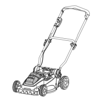
Testing PTO (Power Take Off) Switch
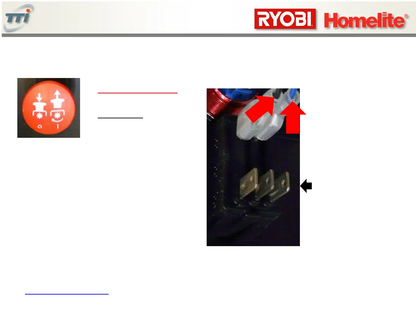
3. Insert DMM probes where indicated.
When red button is PULLED OUT, the
switch is CLOSED (very LOW resistance or
continuity) typically 0 Ohms
4. When red button is PUSHED IN, the
switch is OPEN (very HIGH resistance or
no continuity) typical 12K Ohms when in circuit or open
when removed from circuit.
Note: Make sure
spade lugs are
secure. They should
be locked in place
and should not come
loose if the wires are
pulled on.
Note: 3 terminals are not connected
1. Mower Power OFF
2. DMM set to measure
Resistance
18
5V
< Table of Contents

 Loading...