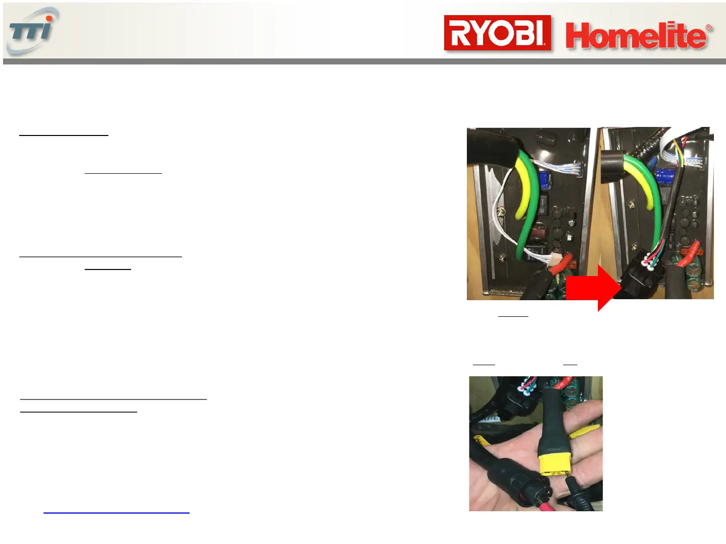
Testing Master and Slave Blade Controllers
Note: Master Controller is identified by
additional large square connectors as shown
above.
Slave Controller does not have these connector
Test for short circuit:
1. Disconnect all connectors to Master Controller.
2. Temporarily touch a wire between heavy red “+” and heavy black “-” wires to drain capacitance.
3. Set DMM to Resistance Mode.
4. Connect DMM probes to heavy red wire (power)
and heavy black (ground) wire to check for short circuit
Typical resistance: 1.56M Ohms
Check resistance of controller output:
1. Set DMM to Resistance Mode.
2. Check continuity between any two terminals .
3. Check continuity between other terminals.
4. Both measurements should be nearly identical.
Typical resistance: 18K-20M Ohms
Test Power and Ground to output circuitry
Set DMM to “Diode” mode
1. Connect black lead of DMM to heavy RED wire (ground).
2. Sequentially connect the black probe to each pin.
DMM should measure approx. 0.48V for each pin (indicating diode good).
31
< Table of Contents
 Loading...