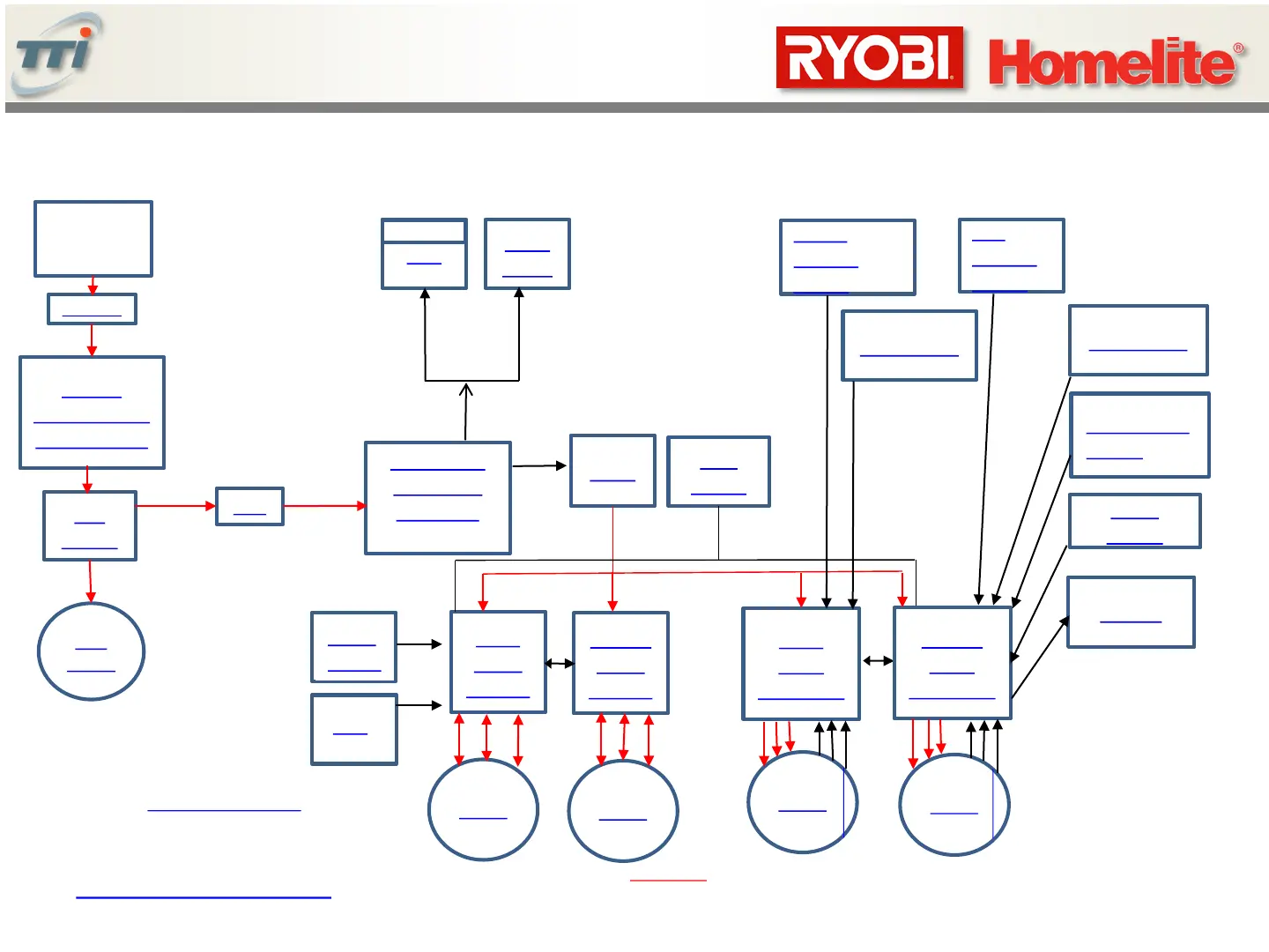
ZTR Block Diagram And Control Flow
48V
Batteries
Main Fuse
Charge
Port/lockout/
battery temp
48V to 12V
(DC to DC)
converter
Relay
Fuel
Gauge
Brake
Switch
Beeper
Seat
switch
Fuse
Master
Blade
Control
Slave
Blade
Control
Motor
Motor
Head
Lights
Accelerator
Note: A detailed wire harness diagram is
located later in this document
USB
Important: Master and slave have
a communication link. If one blade
motor or controller fails, BOTH will
shut down.
< Table of Contents
48V
Slave
Drive
Controller
Accelerator
P
PTO
P
Drive Speed
Switch
P
Blade
Speed
Key
Switch
12V
Left
Neutral
switch
5V out
7
Motor
Hall Sensors
Master
Drive
Controller
Motor
Hall Sensors
RIGHT
Neutral
switch
Enable
 Loading...