EasyManuals Logo

Siemens LOGO! 230RC User Manual

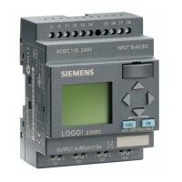
Siemens LOGO! 230RC
236 pages
To Next Page IconTo Next Page
To Previous Page IconTo Previous Page
Page #177 background imageLoading...
Page #177 background image
169
LOGO! Manual
A5E00067781 01
8.4.2 Previous Solution
Various kinds of control systems are used to operate auto-
matic gates. The circuit diagram shows
one
possible gate
control circuit.
K1 K5
K3
S1
Open Close
S0
K3K2
Flashing light
Auxiliary circuit
L1
N
K1
H1
K4
S5 p
>
K6
K6
K1
S2
S2 K3
K2 K4
Open Close
K5
S5 p
>
S1
K3 K1
S4S3
Wiring of the gate control system with LOGO! 230RC
L1 N I1 I2 I3 I4 I5 I6
Q1 Q2 Q3 Q4
SIEMENS
K1 K3
Open Close
S4S3
L1
N
S1
S2 S0
S5
p
>
S5
p
>
Flashing light
H1
Open Close Stop
LOGO! 230RC
Applications

Table of Contents

Questions and Answers:

Question and Answer IconNeed help?

Do you have a question about the Siemens LOGO! 230RC and is the answer not in the manual?

Siemens LOGO! 230RC Specifications

General IconGeneral
Inputs8 digital inputs
Outputs4 relay outputs
Mounting TypeDIN rail
Protection TypeIP20
Dimensions90 x 72 x 55 mm
Output Current10 A
Operating Temperature0°C to 55°C
Power Supply115/230V AC
Storage Temperature-40°C to +70°C

Related product manuals