Overview
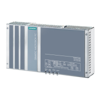
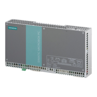
1.2 Design of the device
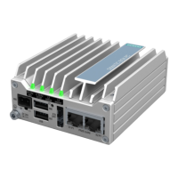
SIMATIC IPC427D
Operating Instructions, 05/2017, A5E31347215-AB
19
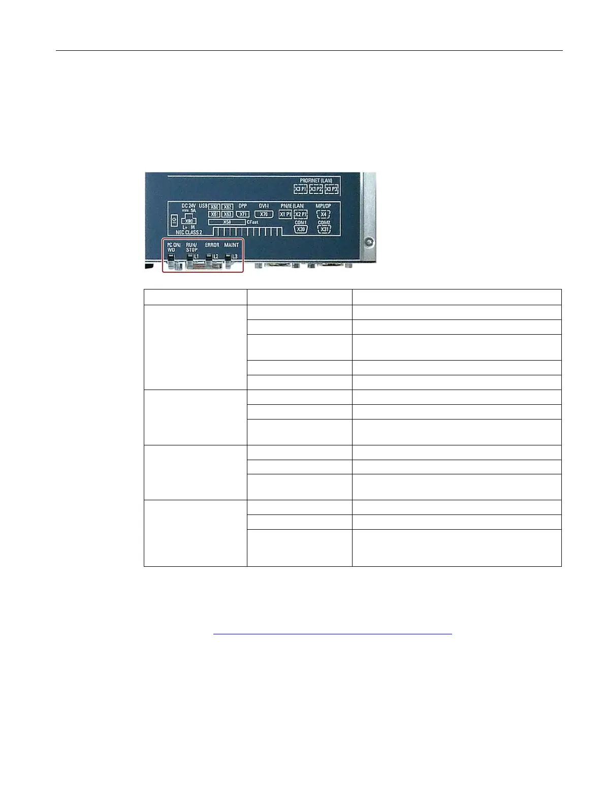
Status displays
Device with PROFIBUS
PC ON/WD
Flashing green/yellow
BIOS in POST, power switch on
Watchdog status display: active
RUN/STOP / L1
Can be controlled by user program
Yellow Can be controlled by controller program (e.g.
WinAC)
ERROR / L2
Red -
Flashing red Can be controlled by user program or controller
MAINT /
L3
Red Can be controlled by controller program
(e.g. WinAC) and shows group errors of the on-
For additional information on controlling the LEDs or the MRAM with a Windows operating
system, please refer to Output register user LED L1/L2/L3 (read/write, address 404Eh)
(Page 135). Example programs for controlling the LEDs on Windows operating systems are
available on the Customer Support page of Siemens Industry Automation and Drive
Technologies. (http://www.siemens.com/automation/service&support)
 Loading...