3.2 Operator controls
3.2.1 Service and operating mode switches
DIP switches
The SIMOTION D410 features operating mode and service selector switches at the bottom of
its front side (see Overview of operator controls and indicators (Page 35)). These function
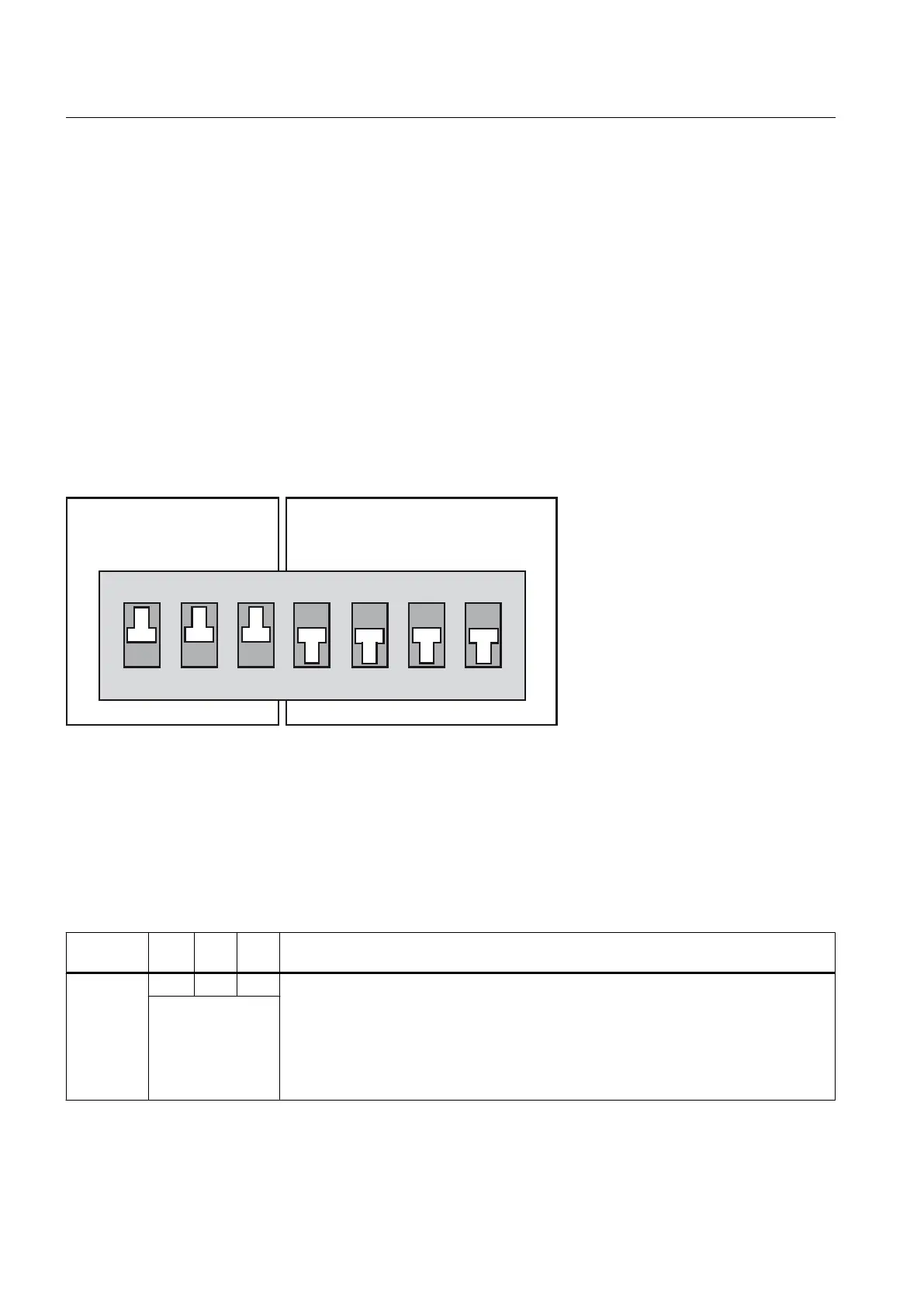
using a DIP switch (DIP = Dual In Line Package), where:
● switches S1 to S3 set the operating mode and
● switches S4 to S7 select the service functions
During "normal" operation, the switch settings shown in the figure below must be retained.
6ZLWFKVHWWLQJ 21
6ZLWFKVHWWLQJ 2))
0RGHVHOHFWRUVZLWFK
6WR6
6HUYLFHVHOHFWRUVZLWFK
6WR6
2
1
Figure 3-2 DIP switches (factory setting)
The modes and service functions that can be set are outlined below.
Mode selector switches
The table shows the possible settings for the mode selector switches.
Table 3-1
Mode selector switch settings
Operating
mode
S1 S2 S3 Meaning
RUN 1 1 1 SIMOTION D410 runs the user program and all connected system performances:
● Read process image of inputs.
● Execution of the user programs assigned to the execution system.
● Write process image of outputs.
The technology packages are active in this state. They can execute commands from the
user program.
(three switches =
ON)
Operation (hardware)
3.2 Operator controls
SIMOTION D410
36 Manual, 04/2014
 Loading...


