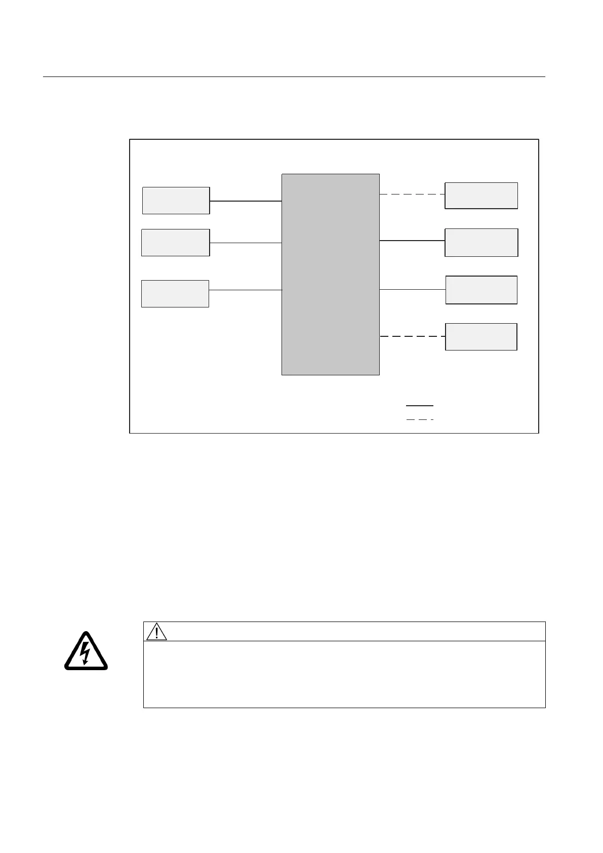
6.4 Overview of SIMOTION D410 connections
6,027,21b'
;
9'&SRZHU
VXSSO\
;
DQG
;
352),1(7
;
;
;
;
;
352),1(7
QRGH
(3WHUPLQDOV
WHPSHUDWXUHVHQVRU
(QFRGHU
'LJLWDOLQSXWV
RXWSXWV
352),%86
'5,9(&/L4
SUHDVVHPEOHGFDEOH
6LQJOHZLUH
352),%86
QRGH
'5,9(&/L4
QRGHV
RQO\LQ6,027,21b'b'3
RQO\LQ6,027,21b'b31
Figure 6-3 Overview of connections
6.5 Connecting the protective ground
Connect SIMOTION D410 to the protective ground. An M4 protective ground screw is available
(see figure "Location of interfaces and front elements in SIMOTION D410" in Chapter
"Description").
The cross-section of the cable running to the protective ground must be at least 10 mm².
1. Remove the M4 protective ground screw.
2. Connect the protective ground and screw the protective ground screw back into the insert
nut (Torx screwdriver, size 20).
WARNING
Danger to life from electric shock due to insufficient grounding
Ensure the connection to the protective ground is low resistance.
Provide a flexible cable to the protective conductor if SIMOTION D410 is mounted on a
movable frame.
Connecting
6.5 Connecting the protective ground
SIMOTION D410
74 Manual, 04/2014
 Loading...


