Interface assignments
Table 4-19
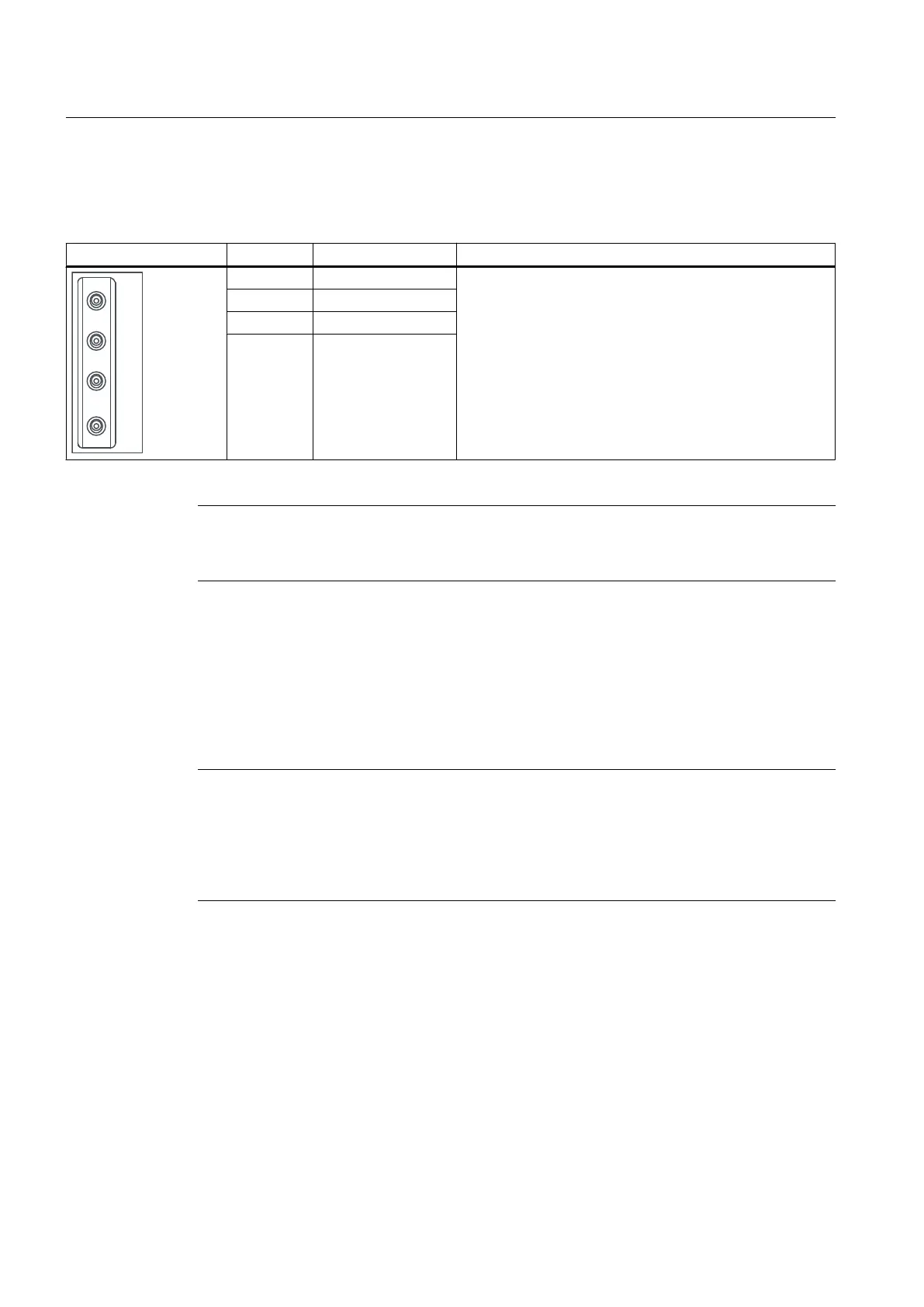
Interface assignments T0, T1 and T2
View Pin Designation Technical details
T0 Measuring socket 0 ● Voltage: 0 V to 5 V
●
Resolution: 8-bit
● Load current: max. 3 mA
● sustained short-circuit proof
● Reference potential is G terminal
T1 Measuring socket 1
T2 Measuring socket 2
G Ground
Note
The
test sockets are provided as a support to commissioning and diagnostics; they must not
be connected for normal operation.
4.10
Power Module Interface
SIMOTION D410 can be connected to a SINAMICS S120 PM340 blocksize power module via
the power module interface.
Note
SIMOTION D410 can only be connected to a SINAMICS S120 PM340 blocksize power
module
via the power module interface. A Power Module in chassis format must be connected
via the DRIVE-CLiQ interface (see the section titled Connecting DRIVE-CLiQ components
(Page 76)). A SIMOTION D410 cannot be operated with SINAMICS G120 (PM2x0) Power
Modules. Booksize Motor Modules can likewise not be connected.
See also
SIMOTION D410 mounted on the power module
(Page 62)
Interfaces
4.10 Power Module Interface
SIMOTION D410
60 Manual, 04/2014
 Loading...


